Torque multiplier and method of use

a technology of torque multiplier and multiplier, which is applied in the field of torque multiplier, can solve the problems of shearing of the detent stud, and achieve the effects of increasing the torque, increasing the speed of torsional rotation, and removing the fastener faster

Inactive Publication Date: 2015-09-22
CULLISON ROBERT F
View PDF15 Cites 5 Cited by
  • Summary
  • Abstract
  • Description
  • Claims
  • Application Information

AI Technical Summary

Benefits of technology

[0004]In one aspect of the present invention, a method includes providing a torque multiplier with first and second identical input / output connectors operatively connected by a torque multiplying mechanism, a driving tool, and a socket. The method further includes engaging the driving tool with the first connector and the socket with the second connector, engaging the socket on a fastener, and operating the driving tool to provide an increased torque on the socket to break loose the fastener from a tight position, thereafter flipping the torque multiplier so that the driving tool engages the second connector and the socket engages the first connector, and operating the driving tool to provide an increased speed of torsional rotation to run the fastener along a fastener-engaged shaft to more quickly remove the fastener from the shaft.
[0008]An object of the present invention is to provide a torque multiplier tool that can be selectively used to apply increased torque or used to apply a faster rotational action (with reduced torque).
[0009]An object of the present invention is to provide a torque multiplier tool with integral over-torque preventing device, and where the over-torque preventing device is low cost, easily replaced, and intuitively positioned.
[0010]An object of the present invention is to provide a torque multiplier tool with integral over-torque preventing device, where the over-torque preventing device fails in a non-catastrophic manner for increased safety for the user. For example, the present detent stud, when over-stressed, is designed to fail with a torsional tearing action that distributes the force-versus-resistance curve. Thus, it avoids a sharp snap and quick release of torque-resisting forces, which can surprise a user and cause the user to lose their balance.

Problems solved by technology

By this arrangement, over-torque stress applied to the detent stud and the torque multiplier mechanism results in shearing of the detent stud prior to damage occurring to the torque multiplier mechanism.

Method used


Image

  • Torque multiplier and method of use
  • Torque multiplier and method of use
  • Torque multiplier and method of use

Examples


Embodiment Construction

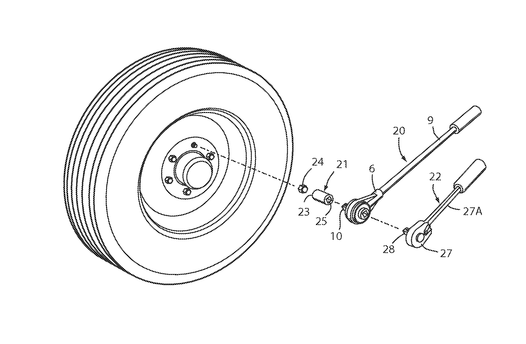
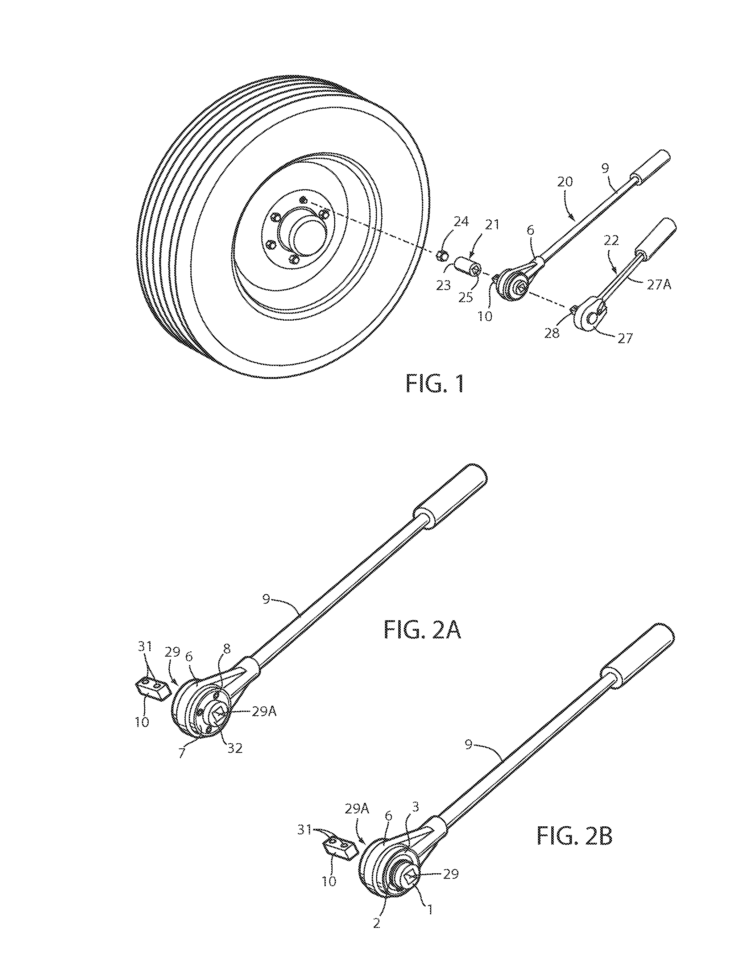
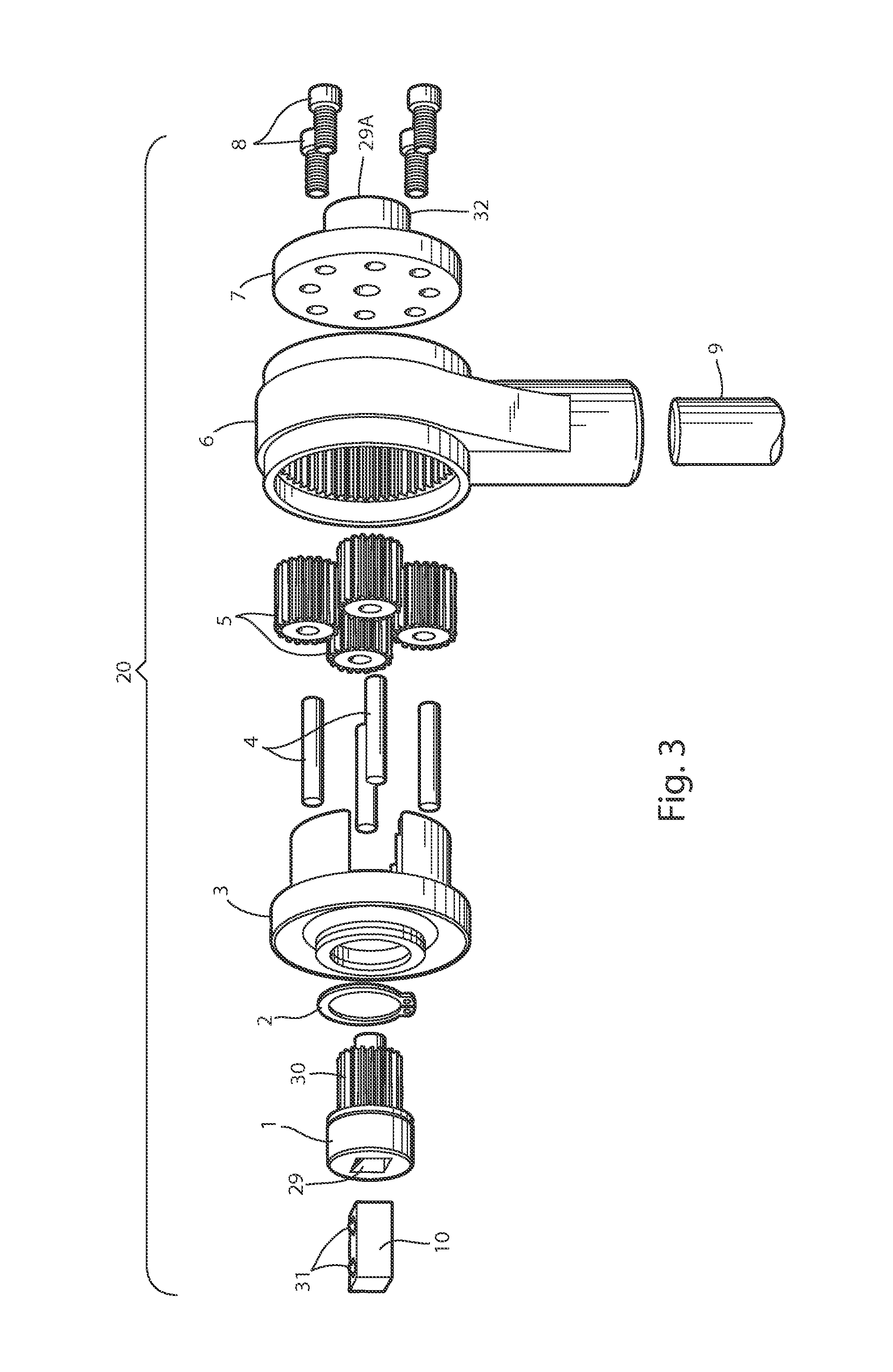
[0016]The present apparatus 20 (FIGS. 1, 2A, 2B) (also called a “torque multiplier tool”) can be used with a socket 21 and driving tool 22 (e.g. ratchet wrench) to apply an increased torque for initially breaking loose (or tightening) a fastener from a tightened position, and then (or alternatively) flipped (i.e. inverted 180 degrees) for thereafter rapidly removing (or assembling) the fastener along a threaded shaft.

[0017]The socket 21 (FIG. 1) includes a body with a first socket opening 23 (connector) on its first end for engaging a fastener, such as a retainer nut (illustrated as a lug nut 24 for securing a vehicle wheel to a vehicle), and a second socket opening 25 (connector) on its other end for engaging a square-shafted double detent stud 10 of the torque multiplier tool 20. A size and shape of the detent stud 10 is standardized in the tool industry.

[0018]The driving tool 22 (FIG. 1) includes a ratchet body end 27 with square-shafted protrusion 28 having a shape similar to th...


PUM


Abstract

A torque multiplier apparatus includes an input pinion, a geared torque multiplier mechanism, and an input retainer. The input pinion and the input retainer include first and second identical connectors so that a detent stud can be positioned in either one of the first and second connectors, allowing the torque multiplier to be used for increased torque (and reduced speed) or for increased speed (and lesser torque). A related method includes engaging the driving tool with the first connector and the socket with the second connector to provide an increased torque on a socket to break loose a fastener, and flipping the torque multiplier so that the driving tool engages the second connector and the socket engages the first connector to provide an increased speed of torsional rotation to more quickly remove the fastener from the shaft. The detent stud is torsionally shearable, thus preventing over-stressing and damaging the tool.

Description

[0001]This application claims benefit under 35 USC §119(e) of provisional application Ser. No. 61 / 673,761, filed Jul. 20, 2012, entitled TORQUE MULTIPLIER AND METHOD OF USE, the entire contents of which are incorporated herein by reference.BACKGROUND[0002]The present invention relates to torque multipliers, and more particularly relates to a first tool useful for multiplying torque applied by a mating second tool, the first tool being reversible so that the torque can be multiplicatively increased (resulting in reduced torsional speed) or decreased (resulting in increased torsional speed).[0003]Torque multiplier tools are known. However, improvements are desired in terms of robustness of the assembly, and multi-functionality so that the tool can be used both for applying increased output torque (with lower speed output) for initially breaking loose a fastener from a tightened position, and for applying a decreased output torque (with higher speed output) for rapidly removing the fas...

Claims


Application Information

Patent Timeline
Patent Type & Authority Patents(United States)
IPC IPC(8): B25B17/02B25B23/142B25B23/14B25B23/00B25B23/153B25B17/00B60B29/00
CPCB25B17/02B25B17/00B25B23/0007B25B23/142B25B23/1415B60B29/005
Inventor CULLISON, ROBERT F.
Owner CULLISON ROBERT F
Why Eureka
Try Eureka