Channel implant

a technology of channel implants and implants, applied in the field of channel implants, can solve the problems of varying problems in the eye socket, and the need for reconstruction, and achieve the effect of avoiding the need for surgery

Active Publication Date: 2020-06-23
PORIFEROUS
View PDF6 Cites 0 Cited by
  • Summary
  • Abstract
  • Description
  • Claims
  • Application Information

AI Technical Summary

Problems solved by technology

In some instances, a variety of problems can occur in the eye socket, ranging from inflammatory diseases or other diseases, tumors, infections, birth defects, or injuries from trauma.
When these problems occur, it may become necessary to reconstruct various portions of the orbital socket, including the orbital floor and / or the supraorbital ridge.

Method used


Image

  • Channel implant
  • Channel implant
  • Channel implant

Examples


Embodiment Construction

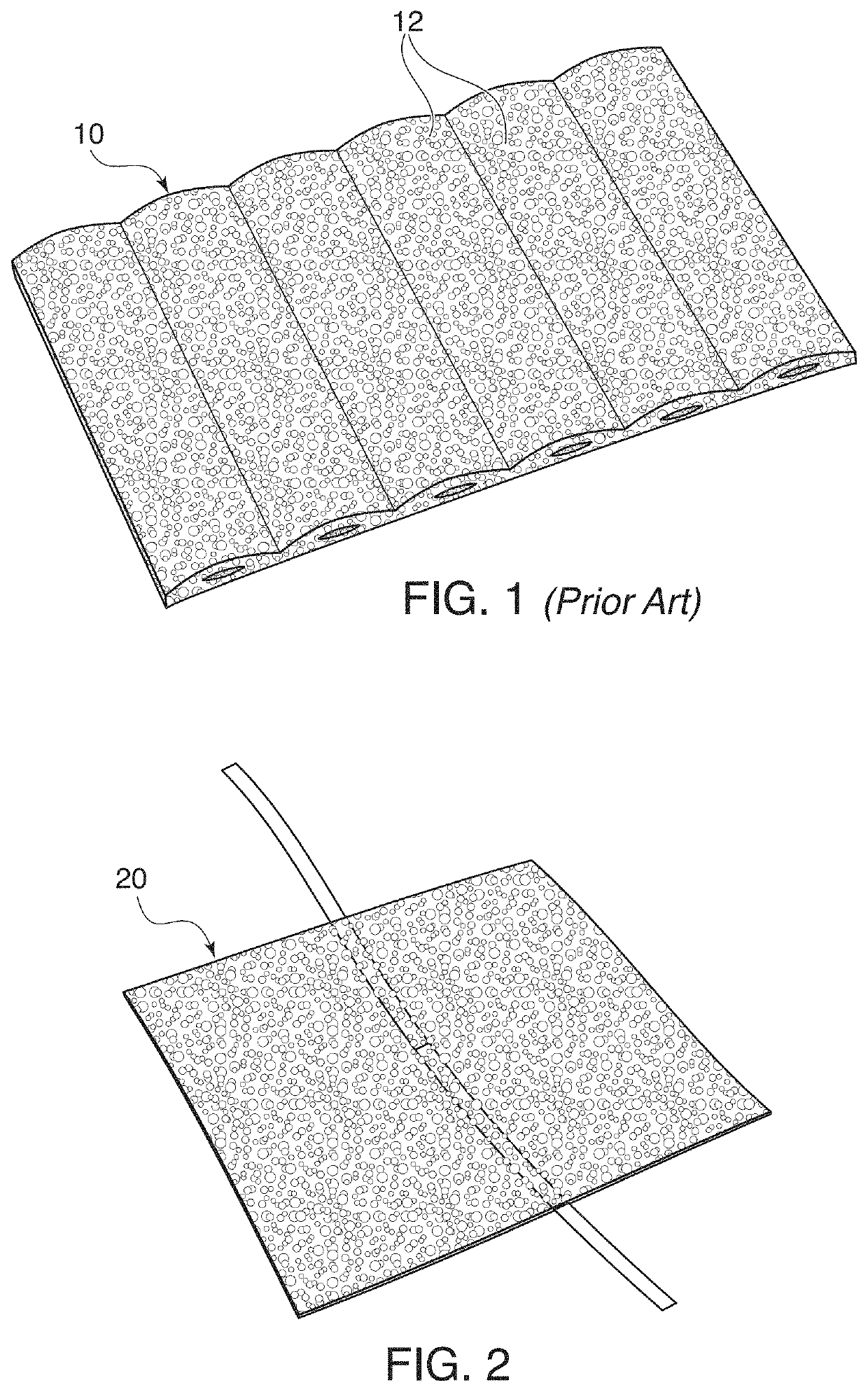
[0025]Embodiments of the present invention provide channel implants that are designed for repair of the orbital floor and wall trauma (or damage / trauma to surrounding bones, i.e., the brow bone ridge). The implants may be used where the addition of one or more rigid fixation plates are needed to offer structural support. In some examples, the implant may be cut to the desired shape.

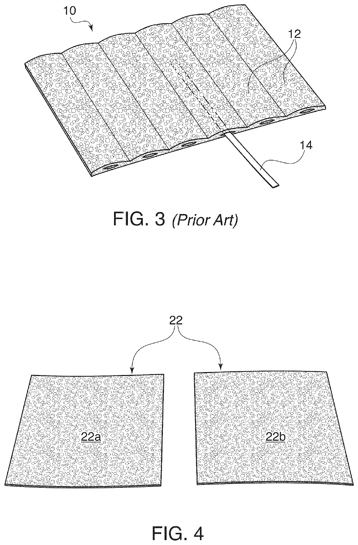
[0026]For prior implants, after the implant has been cut to shape, a fixation plate is inserted into a channel formed in the implant body. Examples are illustrated by FIGS. 1 and 3. In these examples, the implant 10 has a series of channels 12 that have been pre-formed into the implant. This is illustrated by prior art FIG. 1. The fixation plate may 14 is then inserted through one of the channels 12. The fixation plate 14 can extend out both ends of the implant if desired, as shown by FIG. 3. This figure illustrates the thickness needed to form a channel while providing enough thickness for manufacturing ...


PUM

PropertyMeasurementUnit
thicknessaaaaaaaaaa
thicknessaaaaaaaaaa
thicknessaaaaaaaaaa

Abstract

Embodiments relate generally to channel implants used for surgical reconstruction and / or repair. Certain embodiments of the channel implants are designed for craniofacial surgery, reconstruction, and / or augmentation. More specifically, some embodiments find particular use in orbital reconstructive surgery, such as repair of the orbital floor or supraorbital ridge (brow ridge). Embodiments also relate to methods for using and for manufacturing the channel implants disclosed.

Description

CROSS REFERENCE TO RELATED APPLICATIONS[0001]This application claims the benefit of U.S. Provisional Application Ser. No. 62 / 450,724, filed Jan. 26, 2017, titled “Significantly Thin Orbital Floor Implant with Channel,” and U.S. Provisional Application Ser. No. 62 / 549,112, filed Aug. 23, 2017, titled “Micro Channeled Porous Sheet,” the entire contents of each of which are hereby incorporated by reference.FIELD OF THE DISCLOSURE[0002]Embodiments of the present disclosure relate generally to channel implants used for surgical reconstruction and / or repair. Certain embodiments of the channel implants are designed for craniofacial surgery, reconstruction, and / or augmentation. More specifically, some embodiments find particular use in orbital reconstructive surgery, such as repair of the orbital floor or supraorbital ridge (brow ridge). Embodiments also relate to methods for using and for manufacturing the channel implants disclosed.BACKGROUND[0003]The orbit is the boney socket in the skul...

Claims


Application Information

Patent Timeline
Patent Type & Authority Patents(United States)
IPC IPC(8): A61F2/28A61B17/84A61L27/12A61F2/30
CPCA61F2/2875A61F2/2846A61F2002/2878A61F2002/30011A61B17/842A61F2002/2835A61F2002/3008A61F2002/30578A61L27/12A61F2002/3092A61F2310/00023A61F2002/30971A61F2002/30968A61F2002/3096A61F2002/30576A61F2/0059A61B90/02A61F2210/0076A61F2250/0098
Inventor NOBLE, AARONBURNSTINE, MICHAEL A.
Owner PORIFEROUS
Why Eureka
Try Eureka