
Steering control device

a control device and steering technology, applied in the direction of electric steering, power steering, vehicle components, etc., can solve the problems of unsatisfactory steering feeling and unsatisfactory controllability

Active Publication Date: 2020-07-07
JTEKT CORP
View PDF21 Cites 0 Cited by
  • Summary
  • Abstract
  • Description
  • Claims
  • Application Information

AI Technical Summary

Benefits of technology

The invention provides a steering control device that accurately transmits the reaction force from the road surface to the steering wheel, resulting in a more satisfying and controllable steering sensation. This is achieved by compensating for the estimated axial force to reflect the road surface reaction force and controlling the rotation angle to the target angle, resulting in torque that is applied to the steering wheel.

Problems solved by technology

Consequently, even if the road-surface reaction force is reflected, the steering angle of the steering wheel is not independently controlled, and thus a situation may occur in which satisfactory steering feeling and satisfactory controllability cannot be obtained because of the reaction force applied to the steering wheel.

Method used


Image

  • Steering control device
  • Steering control device
  • Steering control device

Examples


first embodiment

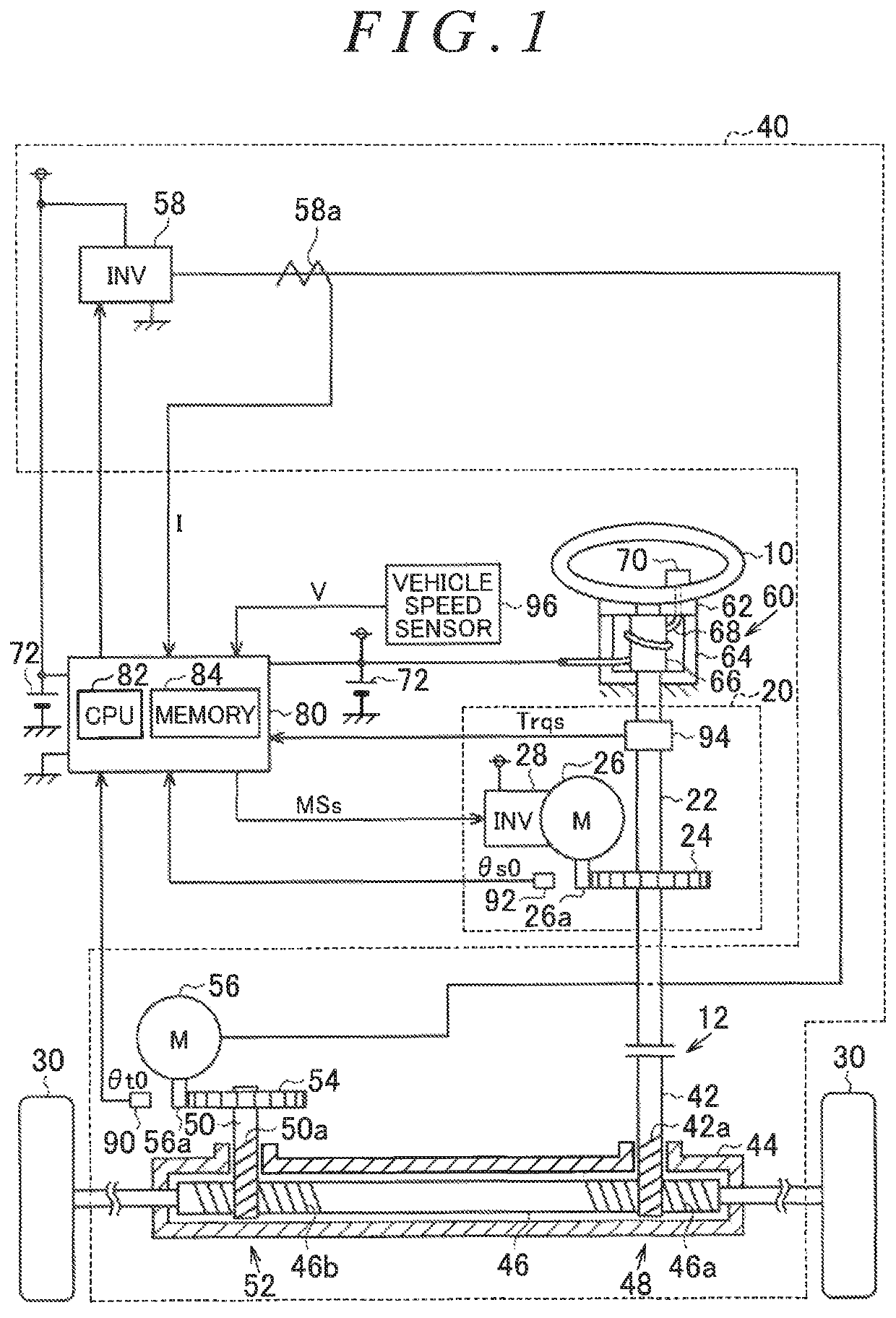
[0021]A first embodiment in which a steering control device of the present invention is embodied as a control device of a steer-by-wire steering system will be described below.

[0022]As depicted in FIG. 1, the steering system includes a reaction force actuator 20 that generates a reaction force acting against operation of a steering wheel 10 and a steering actuator 40 that generates a steering force for steering steered wheels 30 in accordance with operation of the steering wheel 10. Each of the reaction force actuator 20 and the steering actuator 40 is one example of an actuator.

[0023]The reaction force actuator 20 includes a steering shaft 22 fixed to the steering wheel 10, a reaction force-side reduction gear 24, a reaction-force motor 26 having a rotary shaft 26a coupled to the reaction force-side reduction gear 24, and an inverter 28 that drives the reaction-force motor 26. The reaction-force motor 26 is a three-phase brushless motor, for example. The reaction-force motor 26 is ...

second embodiment

[0097]In the second embodiment, the addition circuit M42 is provided. However, the addition circuit M42 may be omitted. In this case, the deviation calculation circuit M46 and the addition circuit M52 may use only the assist torque Trqb*.

[0098]In the second embodiment, the steering torque Trqs is not considered in calculating the estimated axial force Fer. However, the steering torque Trqs may be considered therein. Specifically, the estimated axial force Fer may be obtained by adding the steering torque Trqs to the axial force that is applied to the rack shaft 46 by the steered-side motor 56 and is computed based on the q-axis current Iq. In this case, because the steering torque Trqs is considered, the estimated axial force Fer can be more accurately calculated.

[0099]In each embodiment, the estimated axial force Fer is not limited to the value that is computed based on the q-axis current Iq. The axial force applied to the steered wheels 30 may be directly detected by, for example,...


PUM


Abstract

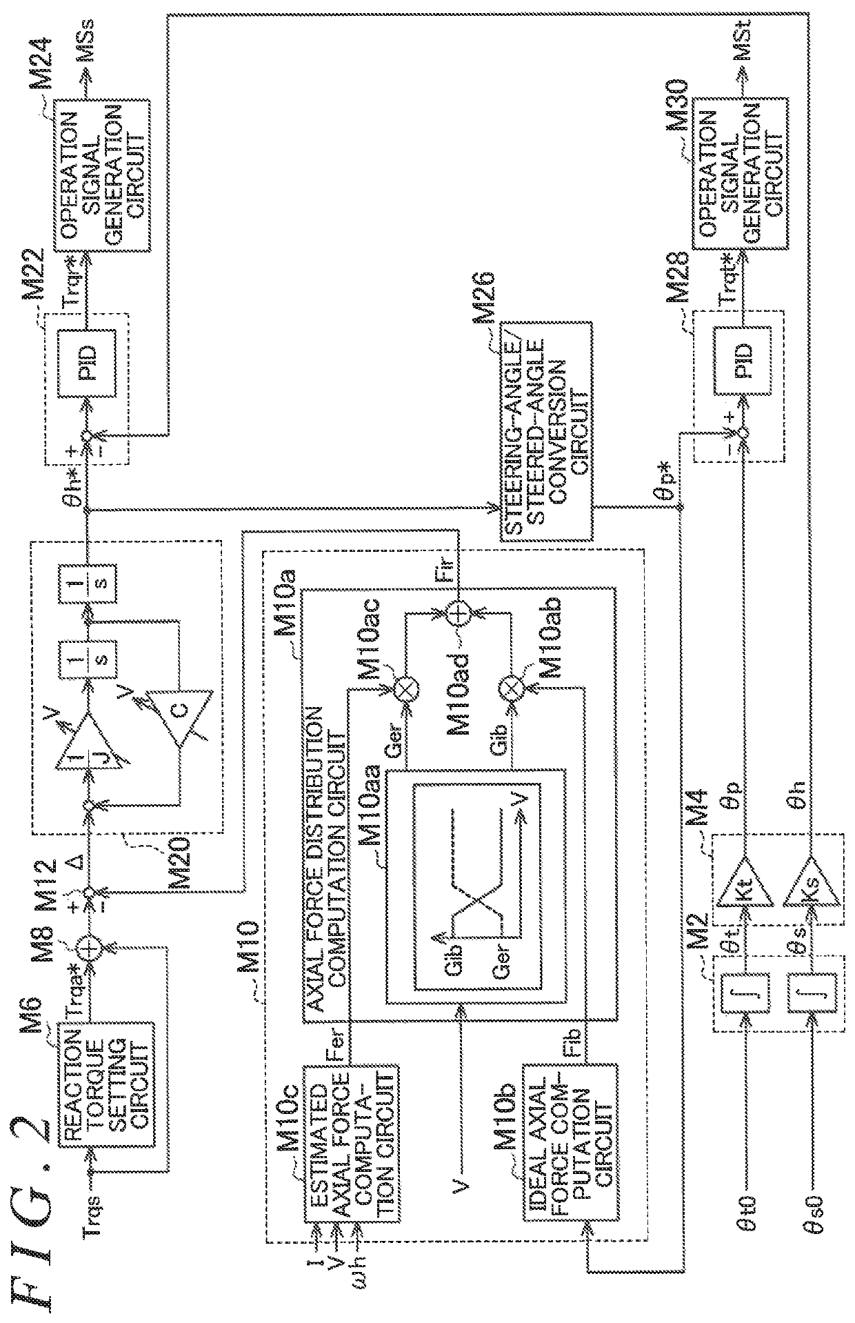
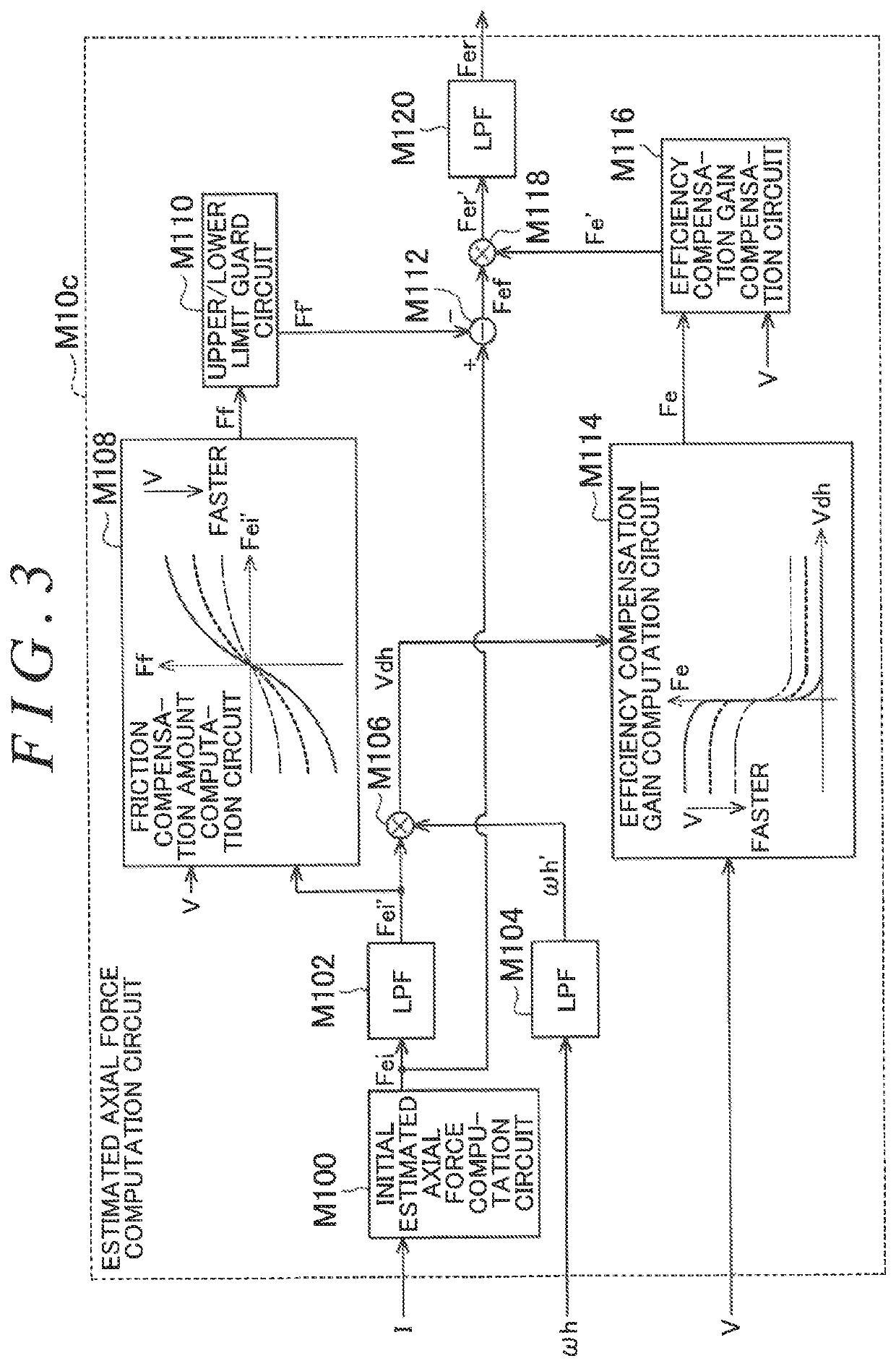
A steering control device that can more appropriately transmit a road-surface reaction force to a steering wheel is provided. The steering control device feedback controls a steering angle to a target steering angle that is a target value of the steering angle. The steering control device includes an estimated axial force computation circuit that computes an estimated axial force so as to reflect a road-surface reaction force in a reaction force generated by a reaction force actuator. The estimated axial force computation circuit computes the estimated axial force by causing a friction compensation amount computation circuit and an efficiency compensation gain computation circuit to compensate an initial estimated axial force computed by an initial estimated axial force computation circuit.

Description

INCORPORATION BY REFERENCE[0001]The disclosure of Japanese Patent Application No. 2016-123803 filed on Jun. 22, 2016 including the specification, drawings and abstract, is incorporated herein by reference in its entirety.BACKGROUND OF THE INVENTION1. Field of the Invention[0002]The present invention relates to a steering control device.2. Description of Related Art[0003]For example, PCT Publication No. WO 2013 / 061568 (WO 2013 / 061568 A1) discloses a steer-by-wire steering system in which a steering wheel and a steered shaft are mechanically separated from each other. The steering system described in WO 2013 / 061568 A1 is configured to apply a reaction force to the steering wheel on the basis of an estimated steering-rack axial force. The estimated steering-rack axial force is obtained by distributing, at a predetermined ratio, an axial force (ideal axial force) in which a road-surface reaction force transmitted from a road surface to steered wheels is not reflected and an axial force ...

Claims


Application Information

Patent Timeline
Patent Type & Authority Patents(United States)
IPC IPC(8): B62D6/00B62D5/04B62D15/02
CPCB62D5/0421B62D5/0412B62D6/008B62D15/024
Inventor KODERA, TAKASHI
Owner JTEKT CORP
Learn More