Shift actuator

a technology of shift actuator and actuator, which is applied in the direction of mechanical equipment, transportation and packaging, etc., can solve the problems of preventing and long time, and achieve the satisfactory responsiveness and controllability of the shift actuator

Active Publication Date: 2015-05-14
HONDA MOTOR CO LTD
View PDF4 Cites 2 Cited by
  • Summary
  • Abstract
  • Description
  • Claims
  • Application Information

AI Technical Summary

Benefits of technology

[0025]By means of the present invention, even with a configuration that the hydraulic control device which is a source of hydraulic supply and the fluid pressure chamber of the shift actuator which is a destination of hydraulic supply are disposed on mutually separated positions, the satisfactory responsiveness and controllability of the shift actuator can be secured.

Problems solved by technology

In this case, however, as well as the conventional configuration, when the orifice portion (small-diameter portion) for controlling flow rate of hydraulic oil fed into the shift actuator is provided on the oil passage in the hydraulic control device, it takes a long time until the hydraulic oil is filled into the hydraulic pipe connecting the shift actuator with the hydraulic control device and the fluid pressure chamber, which may prevent securing the satisfactory responsiveness and controllability of the shift actuator.

Method used


Image

  • Shift actuator
  • Shift actuator
  • Shift actuator

Examples


Embodiment Construction

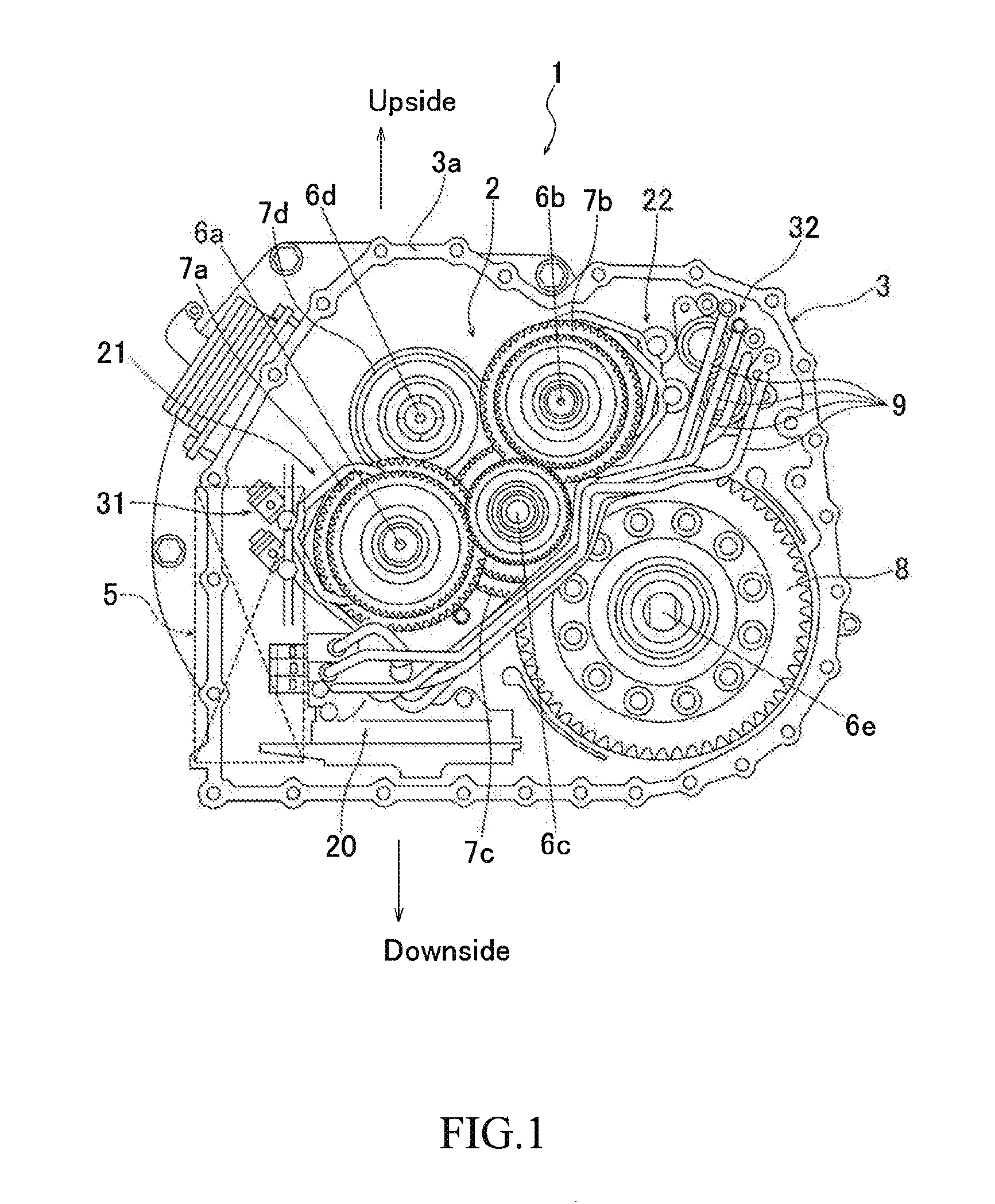
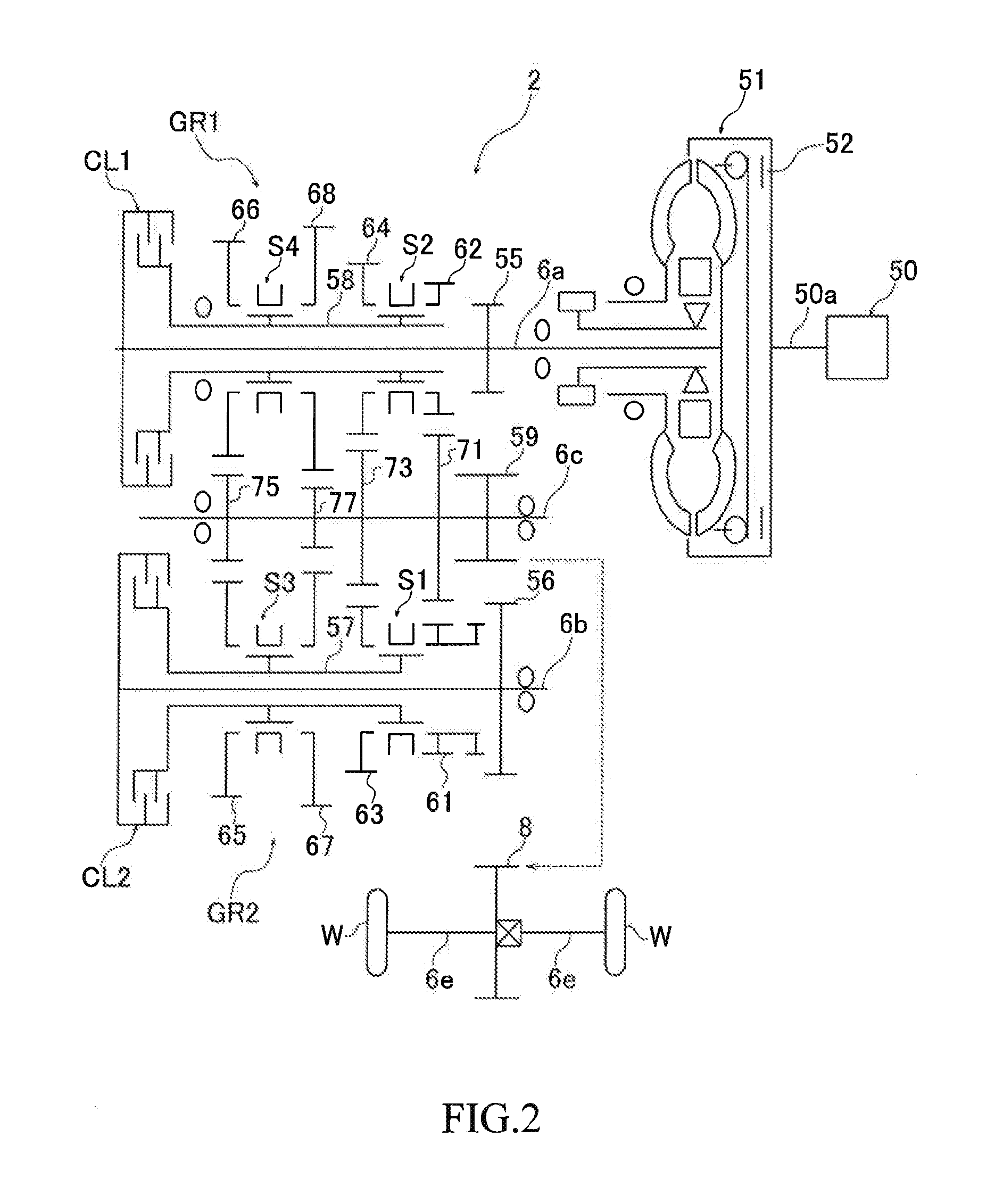
[0034]Embodiments of the present invention are described below in detail referring to the attached drawings. FIG. 1 is a schematic sectional side view showing the example of the whole configuration of a transmission (automatic transmission) including a shift actuator in accordance with an embodiment of the present invention. The transmission 1 shown in the figure includes a gear mechanism 2 installed in a casing 3 and a hydraulic control body (hydraulic control device) 5 mounted on the side of the gear mechanism 2. The gear mechanism 2 includes a first input shaft 6a, a second input shaft 6b, an output shaft 6c, an idle shaft 6d, and a differential shaft 6e disposed mutually parallel to one another, and various kinds of gears for forming a gear shift stage are rotatably installed around each of these rotating shafts 6. Furthermore, FIG. 1 shows the transmission 1 in a state where a transmission case (not shown) surrounding the gear mechanism 2 is removed, with viewed from a front-si...


PUM


Abstract

A shift actuator of the present invention includes a first and a second fluid pressure chamber providing fluid pressure to each of a first and a second piston, a hydraulic control device for regulating pressure of hydraulic oil discharged from a hydraulic source and supplying the same, a first and a second oil passage communicated from the hydraulic control device to each of the first and the second fluid pressure chamber, a first and a second connecting portion for connecting the first oil passage with the first fluid pressure chamber and the second oil passage with the second fluid pressure chamber, and a first and a second orifice portion having a diameter smaller than the inner diameter of the first and the second oil passage provided to each of the first and the second connecting portion.

Description

REFERENCE OF THE RELATED ART[0001]This disclosure relates to the subject involved in Japanese patent application No. 2013-232563 filed on 8 Nov. 2013, and is, as a whole, expressly incorporated to the patent application by the reference.BACKGROUND OF THE INVENTION[0002]1. Field of the Invention[0003]This invention relates to a shift actuator giving fluid pressure to a piston slidably installed in a cylinder, whereby driving a shift operating member for gear shift by the piston.[0004]2. Description of the Related Art[0005]In the conventional art, there are transmissions having a synchronous mechanism for moving a synchro sleeve by a shift fork. And in these transmissions, as shown in Japanese Pat. No. 5280311 (patent literature 1), some have a shift actuator for driving a shift fork. The shift actuator includes a piston slidably installed in a cylinder, a fluid pressure chamber defined opposite to the piston in the cylinder to be supplied with fluid pressure such as oil pressure, and...

Claims


Application Information

Patent Timeline
Patent Type & Authority Applications(United States)
IPC IPC(8): F16H61/30F16H3/38
CPCF16H3/38F16H61/30F16H63/30F16H63/3026Y10T74/19242Y10T74/20024
Inventor ONO, YUKIOKAZAKI, YUJI
Owner HONDA MOTOR CO LTD
Why Eureka
Try Eureka