Spoil treatment plant

a technology for treating plant and spoiler, which is applied in the field of excavating, can solve the problems of reducing the efficiency of vacuum trucks, affecting the quality of vacuum trucks, and limiting the way of disposal, so as to achieve the effect of reducing fouling

Active Publication Date: 2020-07-28
VHS IP PTY LTD
View PDF40 Cites 7 Cited by
  • Summary
  • Abstract
  • Description
  • Claims
  • Application Information

AI Technical Summary

Benefits of technology

[0019]All the elements of the spoil treatment plant are contained within the frame so that the spoil treatment plant is easily relocatable. The frame is suitably of a size to easily fit onto a truck. The frame includes lifting or dragging points so that the entire plant can be lifted onto a flat top truck for easy relocation without disassembly.
[0023]The vibrating screen separator suitably comprises a screen with apertures having a largest dimension of about 1 mm. The apertures preferably have an inverted cone profile to minimise fouling.

Problems solved by technology

The process results in spoil that is mostly slurry that may be about 50:50 water and dirt.
In many countries and regions the slurry is considered to be contaminated and therefore there are limitations on how the disposal can be handled.
This represents a significant cost in transport but also in lost productivity of the vacuum truck.
This process is not available in many places as the water is considered to be contaminated and therefore cannot be allowed to run into the surrounding environment from a holding pond.
Disposal issues associated with hydro-excavation are proving to be a negative impost on the rate of take up worldwide.
Disposal of spoil is a significant time and cost issue.
It does not remove water or further improve the sludge for handling.
In many countries disposal of spoil requires a license, but fewer facilities are able to meet stringent requirements being imposed.
This has a number of implications including:Increased Hydro-excavation costs;Higher disposal costs;Loss of productivity with increased off site time being paid for the disposal process;Loss of production of our client's labour and equipment (time lost duringHydro Vac unit off-site disposal).

Method used


Image

  • Spoil treatment plant
  • Spoil treatment plant
  • Spoil treatment plant

Examples


Embodiment Construction

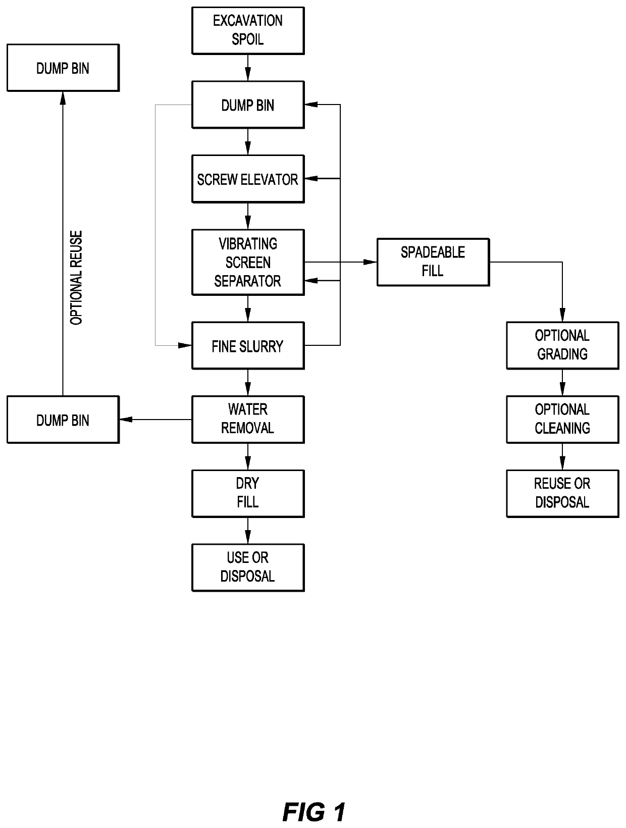
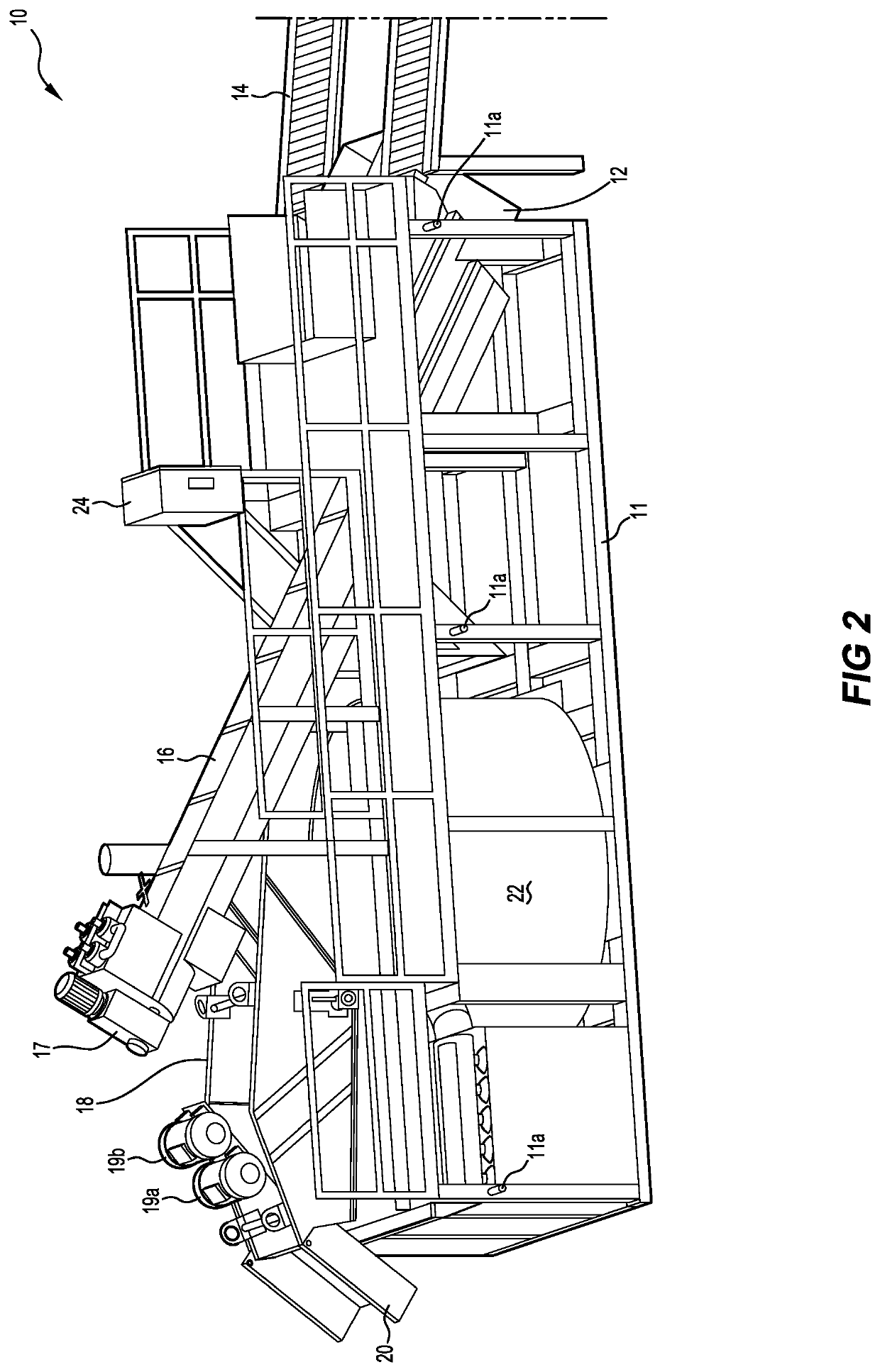
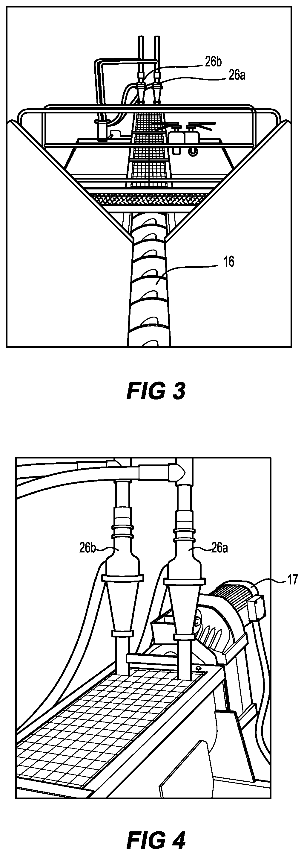
[0045]Embodiments of the present invention reside primarily in a spoil treatment plant and a process for dewatering spoil. Accordingly, the elements have been illustrated in concise schematic form in the drawings, showing only those specific details that are necessary for understanding the embodiments of the present invention, but so as not to obscure the disclosure with excessive detail that will be readily apparent to those of ordinary skill in the art having the benefit of the present description.

[0046]In this specification, adjectives such as first and second, left and right, and the like may be used solely to distinguish one element or action from another element or action without necessarily requiring or implying any actual such relationship or order. Words such as “comprises” or “includes” are intended to define a non-exclusive inclusion, such that a process, method, article, or apparatus that comprises a list of elements does not include only those elements but may include o...


PUM

PropertyMeasurementUnit
aperture diameteraaaaaaaaaa
diameteraaaaaaaaaa
sizeaaaaaaaaaa

Abstract

A spoil treatment plant configured within a frame for easy relocation. The spoil treatment plant comprises a dump bin held within the frame for receiving spoil, a vibrating screen separator mounted in the frame away from the dump bin, an elevator located within the frame, the elevator transporting spoil from the dump bin to the vibrating screen separator, a slurry tank within the frame below the vibrating screen separator that collects slurry; and a chute adjacent the vibrating screen separator that delivers spadeable fill. The vibrating screen separator separates the spoil into spadeable fill delivered from the chute and fine slurry delivered to the slurry tank. The spoil treatment plant may also comprise a further dewatering element, such as a rotary press, that extracts water from the spadeable fill.

Description

FIELD OF THE INVENTION[0001]The present invention relates to the general field of excavation and in particular to the problem of handling spoil, mainly slurries of dirt and water, produced during excavation. More particularly, the invention relates to a method and apparatus for reducing the volume of water in slurry.BACKGROUND TO THE INVENTION[0002]Non-destructive hydro-excavation or vacuum excavation techniques are widely accepted as the safest way to expose or excavate around underground services. In simple terms, a jet of water is blasted into soil to liquefy the soil and then the liquefied soil is sucked up using a vacuum truck. The process results in spoil that is mostly slurry that may be about 50:50 water and dirt. The slurry is waste and needs to be disposed of. In many countries and regions the slurry is considered to be contaminated and therefore there are limitations on how the disposal can be handled. In many cases the slurry must be transported to a suitable location fo...

Claims


Application Information

Patent Timeline
Patent Type & Authority Patents(United States)
IPC IPC(8): B07B1/00C02F11/127B07B13/16B01D37/03B01D21/24B01D21/00B05B1/06
CPCC02F11/127B01D21/2455B07B1/005B01D37/03B05B1/06B07B13/16B07B2230/01B01D21/2477B01D21/0021
Inventor BEACH, JACKCOSTELLO, NEIL
Owner VHS IP PTY LTD
Why Eureka
Try Eureka