Measurer and pip displacement processing program

A technology for measuring instruments and marking points, which is applied in the field of electronic total stations, and can solve problems such as troubles, inability to set up laser plumb instruments, and reduced accuracy of shifting points

Inactive Publication Date: 2006-01-11
KK TOPCON
View PDF4 Cites 16 Cited by
  • Summary
  • Abstract
  • Description
  • Claims
  • Application Information

AI Technical Summary

Problems solved by technology

[0011] Conventionally, laser plummets were installed at the points where the ground marks were to be placed in the case of setting ground marks, moving the ground marks to the ceiling, etc., but there was the following problem: it was not suitable to install the laser plumb at the point as the ground mark. Places where there is a vertical instrument, such as the position of the wall, the inclined surface or the place with large bumps, etc., cannot set up the laser plumb instrument, set the ground mark, move the ground mark on the ground or move the ground mark to the ceiling
[0012] In addition, conventionally, when installing multiple floor marks or moving them to the ceiling, there was a problem that it was necessary to install a laser plumb at each place, which was particularly troublesome.
[0013] Furthermore, when the ground mark is not moved to the vertical position on the ceiling, but the ground mark is moved to a position moved only by a predetermined amount along the horizontal plane, there is also the following problem: it is necessary to start from the ground mark. It is particularly troublesome to measure the horizontal distance and determine the set point by using a scale, and the accuracy of the set point is reduced.

Method used


Image

  • Measurer and pip displacement processing program
  • Measurer and pip displacement processing program
  • Measurer and pip displacement processing program

Examples


Embodiment Construction

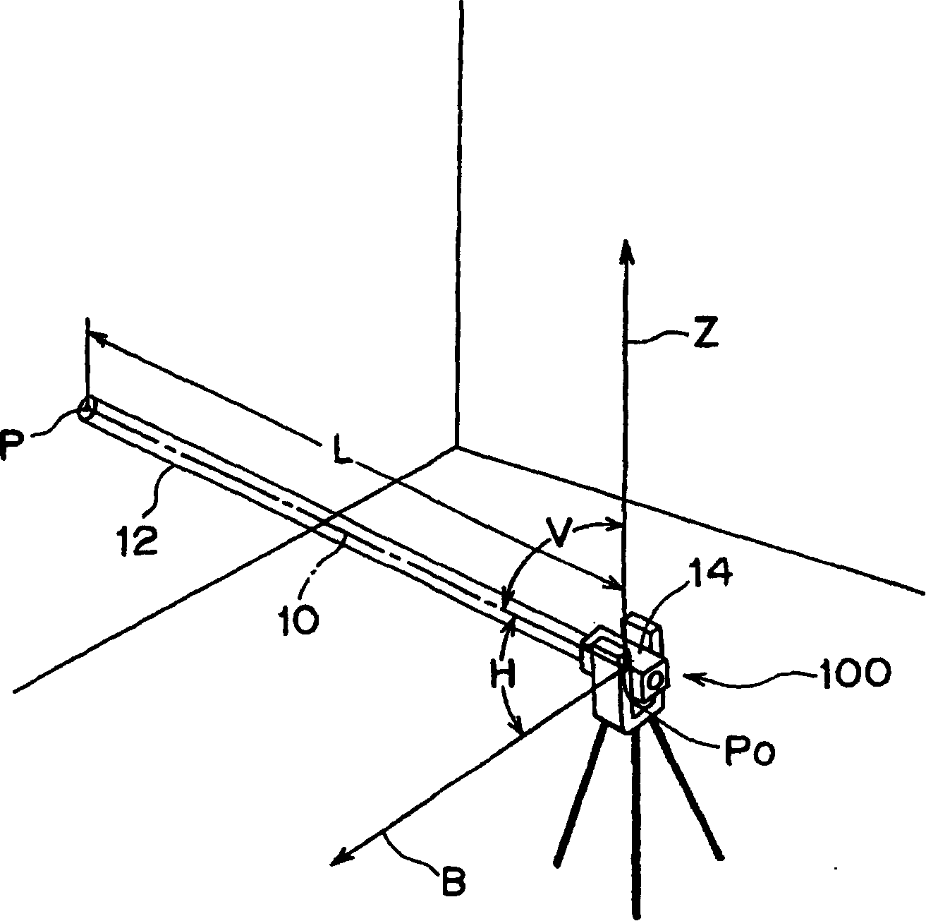
[0033] The present invention uses one measuring instrument including a laser pointer that emits visible laser light coaxially with the collimating axis, and it is possible to set a floor mark, transfer a floor mark to a ceiling, and the like without moving the measuring instrument. Hereinafter, preferred embodiments of the present invention will be described in detail with reference to the drawings.

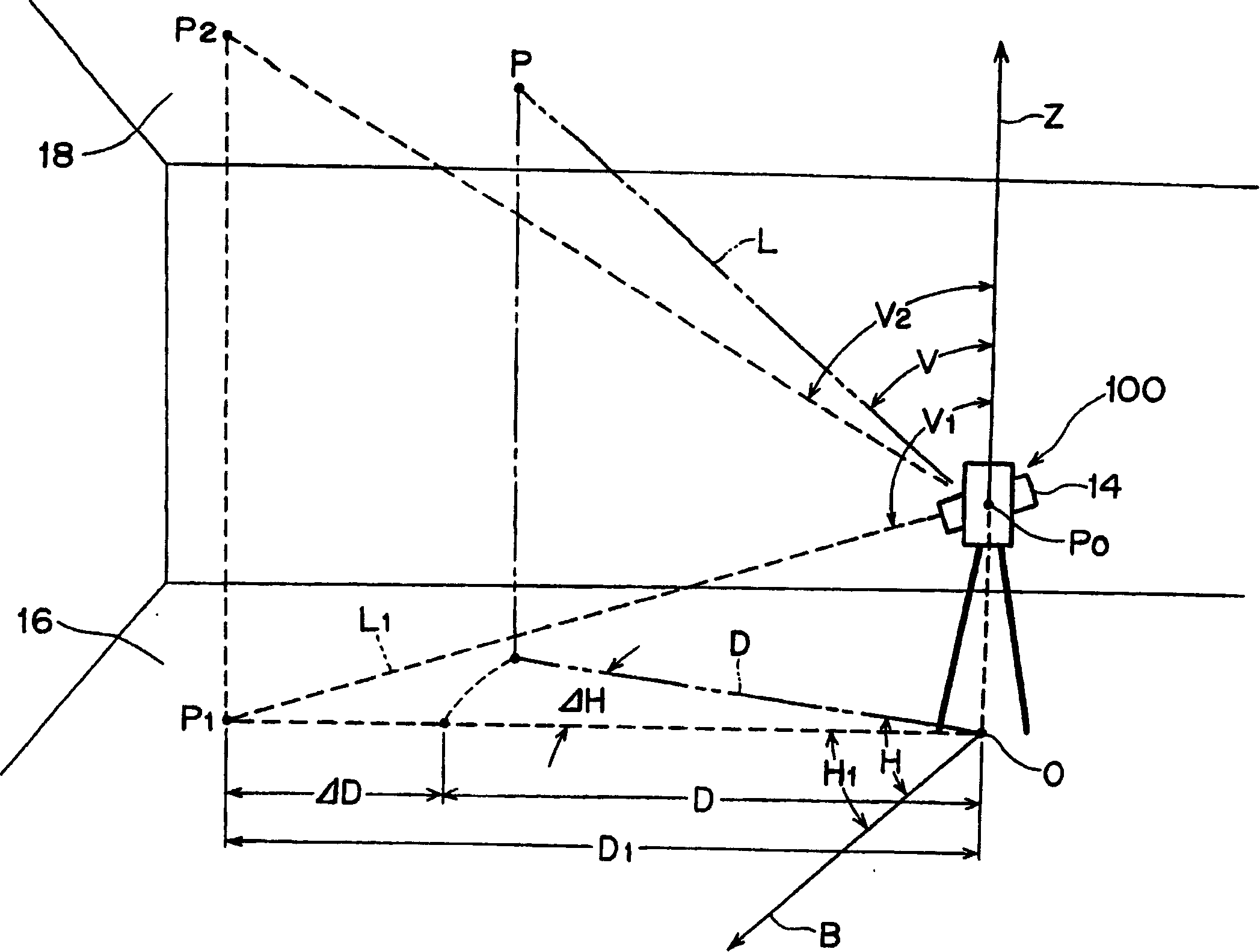
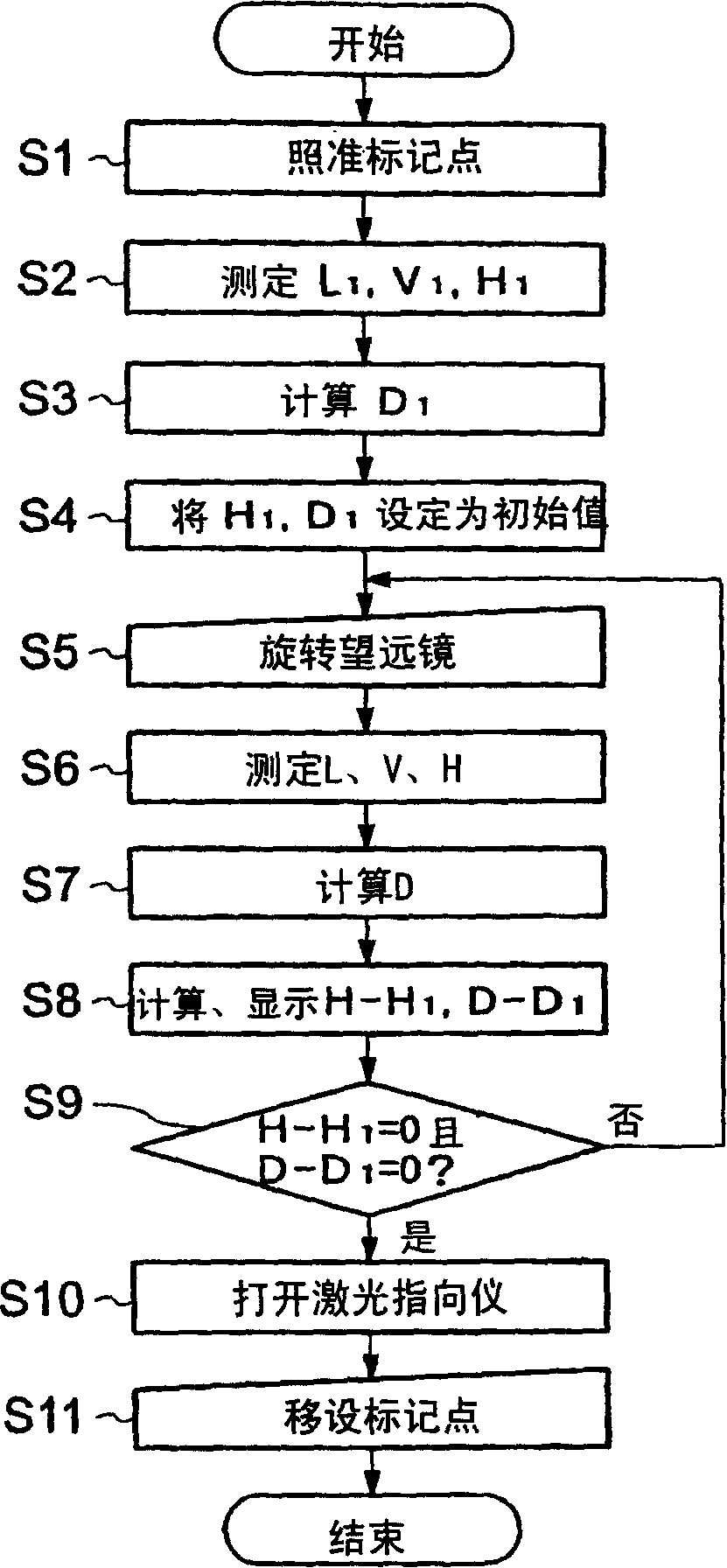
[0034] figure 1 It is a figure explaining the outline|summary of the measuring instrument of one embodiment of this invention. figure 2 It is a figure explaining how to transfer the ground mark to the ceiling using this measuring instrument. image 3 It is a flowchart explaining the procedure for transferring a marker point to a ceiling using this measuring instrument. Fig. 4 is a diagram explaining a method of relocating a ground mark on the ground using the measuring instrument. Figure 5 It is a flowchart explaining a marker point setting procedure for moving a ground mark...


PUM


Abstract

The present invention provides a surveying equipment capable of freely transferring a marking point to a plurality of places in the vertical direction or the horizontal direction, without measuring a horizontal distance by using a measure, without moving this surveying equipment by one surveying equipment. The marking point on a floor surface 16 is collimated by a telescope of the surveying equipment. An oblique distance L1, a horizontal angle and a zenithal angle are measured, and a horizontal distance D1 up to the marking point from a machine point PO is calculated from these measured values, and the horizontal angle H1 and the horizontal distance D1 are set as an initial value. Afterwards, an oblique distance L, a horizontal angle H and a zenithal angle V are measured on a collimation point P by turning the telescope toward the vicinity of a transfer point P2 of the ceiling 18, and a horizontal distance D is determined from these measured values. A deviation ([Delta]D = D-D1) from the initial value of the horizontal distance and a deviation ([Delta]H = H-H1) from the initial value of the horizontal angle are also calculated and displayed. Here, when both deviations [Delta]D and [Delta]H become zero, the transfer point P2 is indicated by a laser pointer.

Description

technical field [0001] The present invention relates to an electronic total station (electronic distance measuring goniometer), and more specifically, to a vertical direction suitable for setting ground marks, moving ground marks to ceilings, and verticality measurement of steel frames (立て入れ). The marker point transfer processing program such as the position acquisition process (position out し construction work). Background technique [0002] In the past, when moving the floor mark to the ceiling, etc., the following method was adopted: using a laser plumb instrument that can emit laser light up and down in the vertical direction, the laser is emitted downward toward the position of the floor mark, and the laser beam is aligned with the ground mark. The positions of the markings coincide with each other, and the upward laser beam is emitted coaxially with the downward laser beam, and the position of the floor mark is transferred to the ceiling (refer to the following patent ...

Claims


Application Information

Patent Timeline
Patent Type & Authority Applications(China)
IPC IPC(8): G01C3/00
Inventor 清水克昭
Owner KK TOPCON
Why Eureka
Try Eureka