Medium discharging device and method of controlling medium discharging device

a technology of discharging device and medium, which is applied in the direction of transportation and packaging, thin material processing, article delivery, etc., can solve the problems of affecting the alignment of the preceding medium, difficult to move the medium to the downstream side of the discharge direction, and difficulty in measuring the downward folding of the medium, etc., to achieve the effect of suppressing reducing the friction between the guide member and the medium, and reducing the damage to the alignment of the medium

Active Publication Date: 2020-08-11
SEIKO EPSON CORP
View PDF28 Cites 4 Cited by
  • Summary
  • Abstract
  • Description
  • Claims
  • Application Information

AI Technical Summary

Benefits of technology

[0006]An advantage of some aspects of the disclosure is to provide a medium discharging device that can reduce folding of a discharged medium.

Problems solved by technology

However, in a printing apparatus disclosed in JP-A-2014-196182, this kind of downward folding is not measured.
This problem is not limited to the printing apparatus and the post-processing device and is common in a medium discharging device that discharges and loads a medium such as a sheet of paper.
Therefore, when the guide member is retracted to the retracted position and the medium is placed on the upper surface of the preceding medium, it is difficult for the medium to be displaced to the downstream side of the discharge direction.
Thus, it is possible to reduce a frequency with which the guide member wrongly comes into contact with the preceding medium, alignment of the preceding medium is damaged, or the preceding medium is damaged.

Method used


Image

  • Medium discharging device and method of controlling medium discharging device
  • Medium discharging device and method of controlling medium discharging device
  • Medium discharging device and method of controlling medium discharging device

Examples


first embodiment

[0067]Hereinafter, a first embodiment of the disclosure will be described with reference to the drawings. In the following drawings, in order to illustrate each member in a recognizable size, the scale of each member is illustrated to be different from an actual scale.

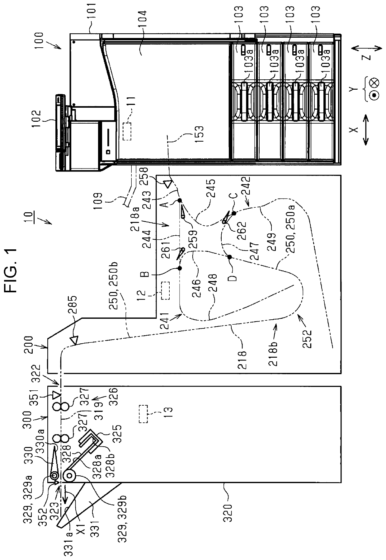
[0068]Further, a configuration of a printing apparatus will be described. As illustrated in FIG. 1, a printing apparatus 10 includes an image forming device 100, an intermediate transporting device 200, and a post-processing device 300. Further, the devices 100, 200, and 300 include control units 11, 12, and 13 that control driving of mechanisms of the devices 100, 200, and 300, respectively. The respective control units 11 to 13 may communicate with each other. For example, the control unit 11 integrally controls the entire printing apparatus 10, and the control units 12 and 13 control the respective devices 200 and 300 according to an instruction of the control unit 11.

[0069]The image forming device 100 is a device t...

second embodiment

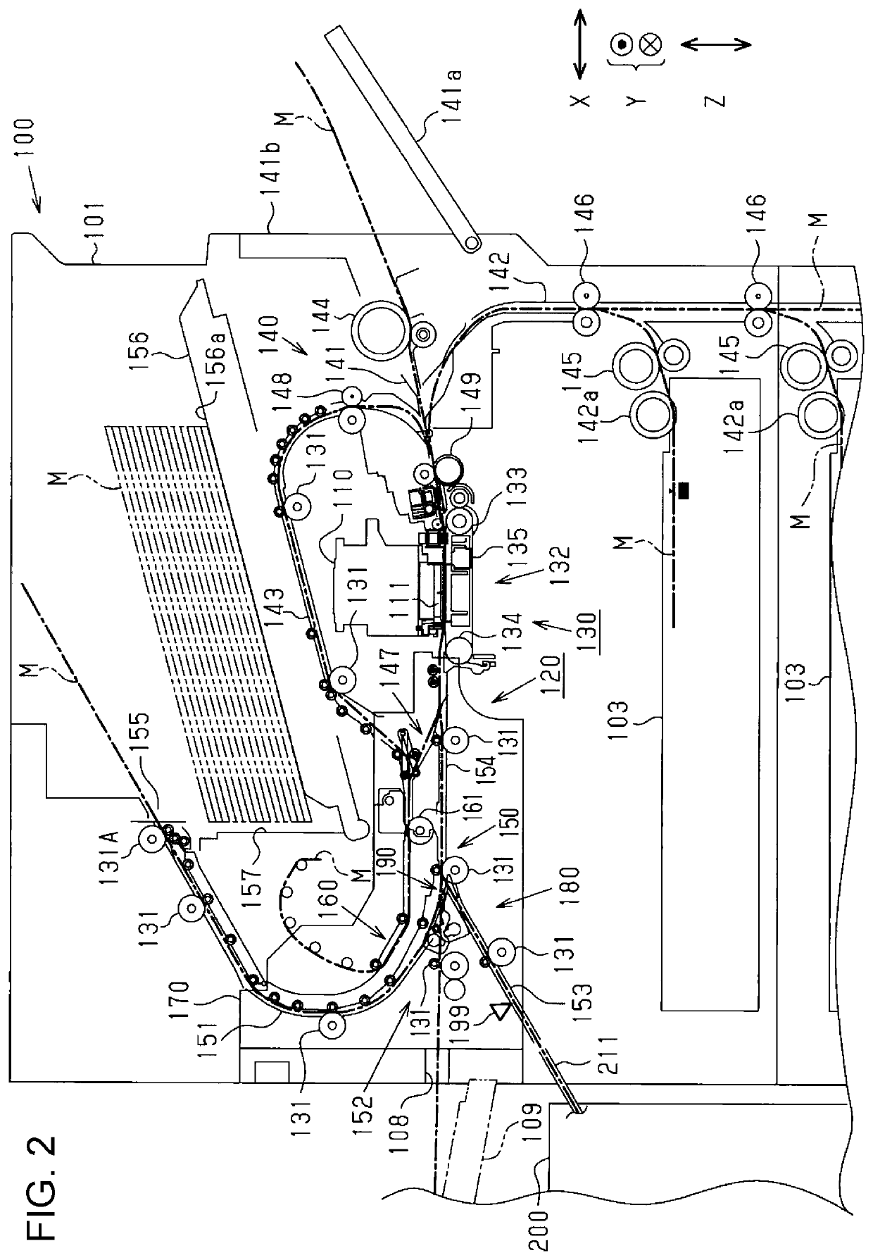
[0183]Next, a medium discharging device according to a second embodiment will be described with reference to FIG. 27. In this second embodiment, the folding preventing device 20, which is the same as that according to the first embodiment, is applied to the image forming device. The folding preventing device 20 guides a single paper sheet M after the printing while the paper sheet M is discharged to the placement stand 156 as an example of a placement portion, and prevents downward folding of the paper sheet M. An image forming device 400 illustrated in FIG. 27 has the same configuration as that of the image forming device 100 according to the first embodiment except that the folding preventing device 20 is provided.

[0184]As illustrated in FIG. 27, in the image forming device 400 as an example of the medium discharging device, the folding preventing device 20, which is the same as that according to the first embodiment, is provided above the placement stand 156 to which the paper sh...


PUM

PropertyMeasurementUnit
heightaaaaaaaaaa
widthaaaaaaaaaa
friction coefficientaaaaaaaaaa

Abstract

A medium discharging device includes a discharge roller pair that discharges a medium, a discharge tray disposed below the discharge roller pair in a vertical direction and having a placement surface on which the discharged medium is placed, and a guide member that is advanced and retracted between an advanced position where the guide member is advanced inward in a width direction from opposite sides in the width direction intersecting a discharge direction of the medium and a retracted position where the guide member is retracted to an end portion position side in the width direction. When the guide member is disposed at the advanced position, an upstream side end portion of the guide member in the discharge direction is disposed between a discharge position by the discharge roller pair and a position of the placement surface of the discharge tray, in the vertical direction.

Description

CROSS REFERENCE TO RELATED APPLICATIONS[0001]The entire disclosure of Japanese Patent Application No. 2017-235470, filed Dec. 7, 2017 is expressly incorporated by reference herein.BACKGROUND1. Technical Field[0002]The present disclosure relates to a medium discharging device that discharges a medium such as a sheet of paper and loads the discharged medium on a placement portion such as a discharge tray.2. Related Art[0003]In the related art, a printing apparatus including a transport portion that transports a medium such as a sheet of paper and a recording head that performs print on the medium has been widely known (for example, JP-A-2014-196182). A discharge tray is provided below a discharge port provided in a housing of the printing apparatus, and the medium after the printing, which is discharged from a discharge roller, is loaded on a placement surface of the discharge tray.[0004]For example, in the printing apparatus (an example of a medium discharging device) disclosed in JP...

Claims


Application Information

Patent Timeline
Patent Type & Authority Patents(United States)
IPC IPC(8): B65H29/52B65H29/38B65H31/30B65H29/34B65H31/10
CPCB65H29/34B65H31/10B65H29/38B65H31/3018B65H29/52B65H2701/1829B65H2404/693B65H2301/4213B65H2404/152B65H2801/06
Inventor KONDO, KATSUYUKIMIYAKAWA, MASAYOSHIOKAMOTO, KATSUMI
Owner SEIKO EPSON CORP
Why Eureka
Try Eureka