Check patentability & draft patents in minutes with Patsnap Eureka AI!

Physical quantity sensor, physical quantity sensor device, composite sensor device, inertial measurement unit, electronic apparatus, and vehicle

a sensor device and physical quantity technology, applied in speed measurement using gyroscopic effects, instruments, surveying and navigation, etc., can solve the problems of moving portion and acceleration sensor not working as acceleration sensor, and achieve high accuracy

Active Publication Date: 2020-08-11
SEIKO EPSON CORP
View PDF10 Cites 0 Cited by
  • Summary
  • Abstract
  • Description
  • Claims
  • Application Information

AI Technical Summary

Benefits of technology

The invention aims to provide sensors and devices that can measure physical quantities accurately without causing excessive displacement of the measuring part. This includes sensors for inertial measurement and vehicle positioning, as well as electronic apparatuses such as smartphones and tablets. The technical effect is to improve the accuracy and efficiency of the sensor devices, making them more reliable and useful in various applications.

Problems solved by technology

However, in the acceleration sensor in JP-A-2007-139505, in a case where acceleration in a direction (Z axis direction) perpendicular to the substrate is applied, the movable portion is excessively displaced in the Z axis direction, and thus the movable portion is damaged due to stress caused by the displacement, or the movable portion is brought into contact with the substrate such that so-called “sticking” occurs in which the movable portion is stuck to the substrate.
Therefore, there is a problem in that there is concern that the acceleration sensor may not function as an acceleration sensor.

Method used


Image

  • Physical quantity sensor, physical quantity sensor device, composite sensor device, inertial measurement unit, electronic apparatus, and vehicle
  • Physical quantity sensor, physical quantity sensor device, composite sensor device, inertial measurement unit, electronic apparatus, and vehicle
  • Physical quantity sensor, physical quantity sensor device, composite sensor device, inertial measurement unit, electronic apparatus, and vehicle

Examples


first embodiment

[0066]First, a physical quantity sensor according to a first embodiment will be described.

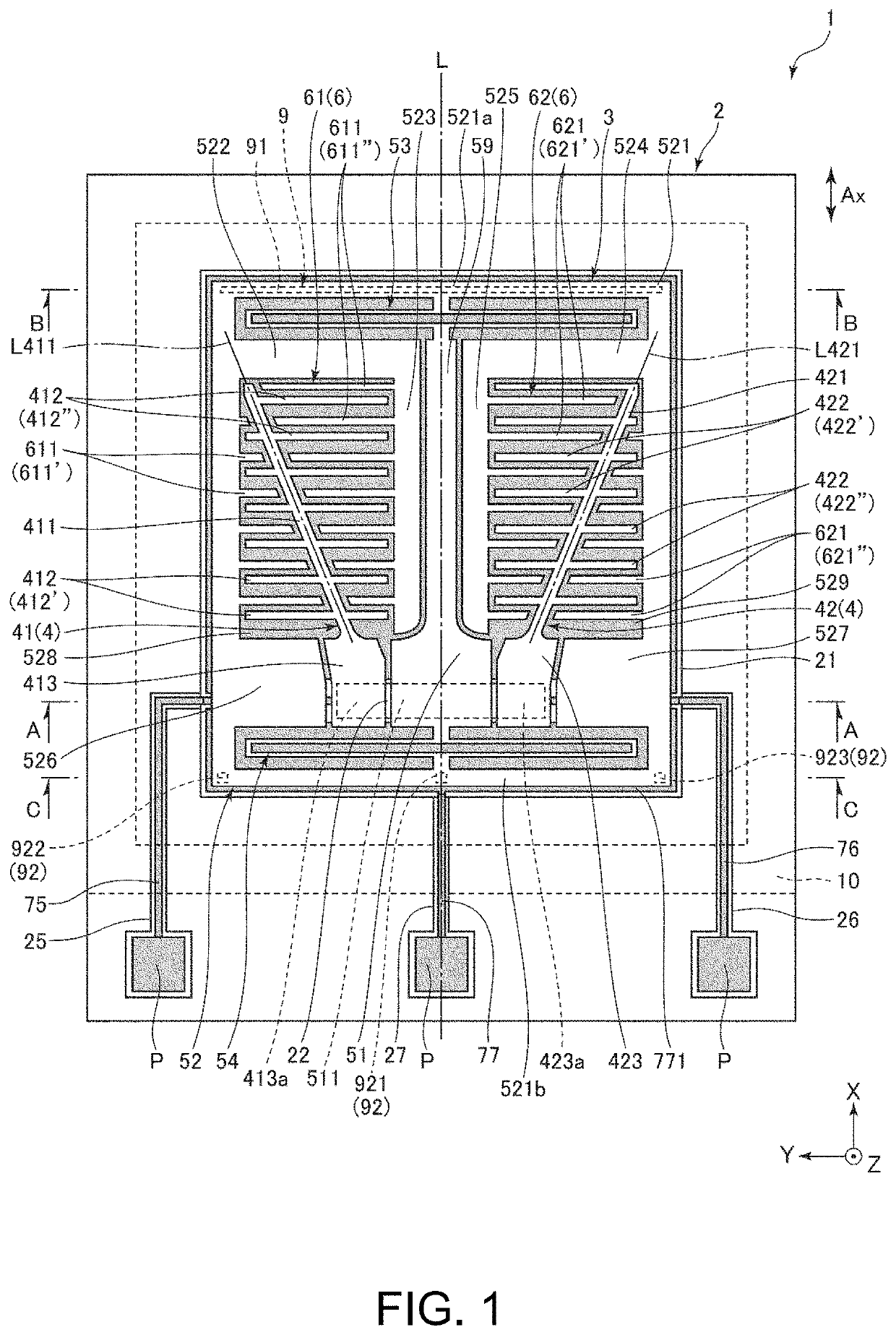
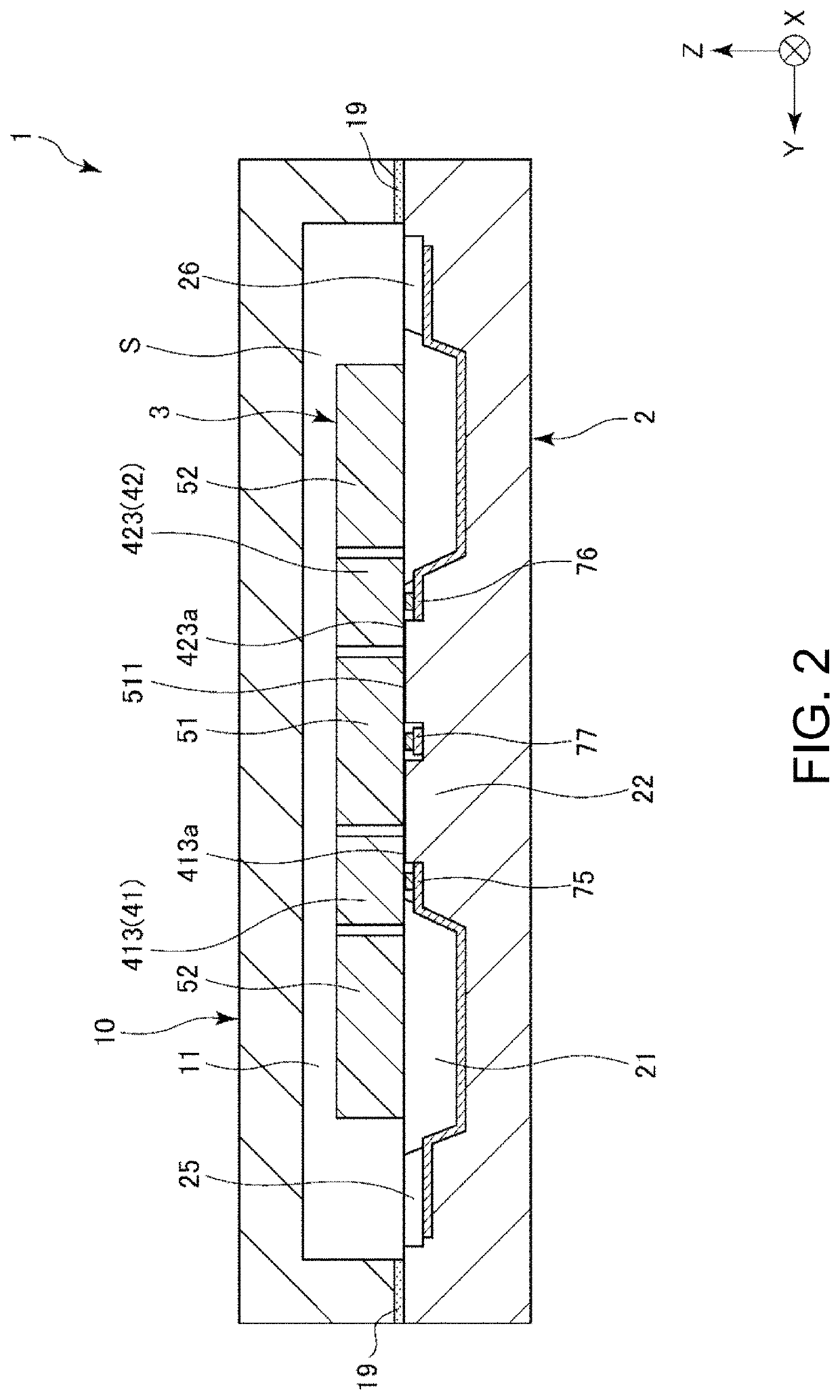
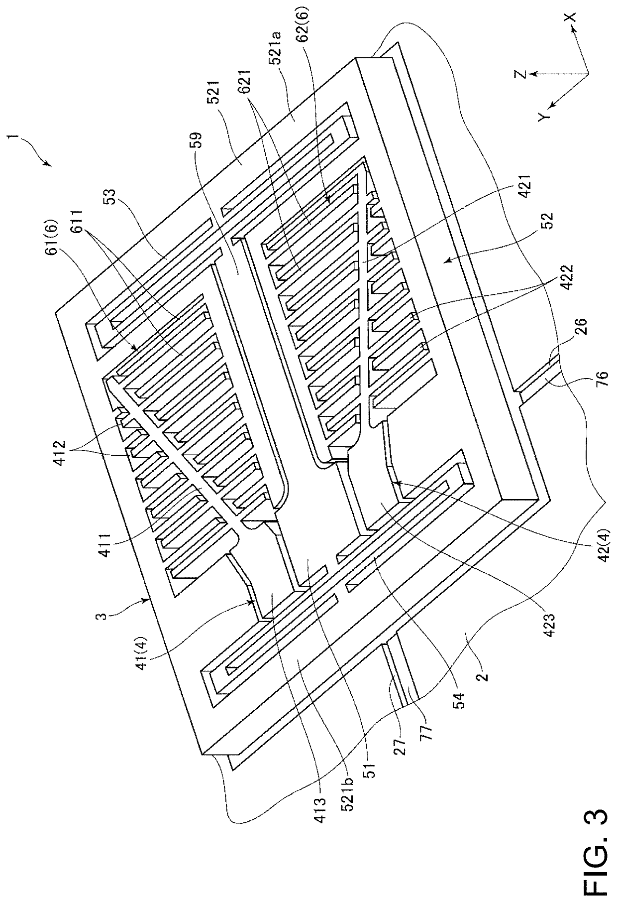
[0067]FIG. 1 is a plan view illustrating a physical quantity sensor according to the first embodiment. FIG. 2 is a sectional view taken along a line A-A in FIG. 1. FIG. 3 is a perspective view of the physical quantity sensor illustrated in FIG. 1. FIG. 4 is a diagram illustrating voltages applied to the physical quantity sensor illustrated in FIG. 1. FIG. 5 is a sectional view taken along a line B-B in FIG. 1. FIG. 6 is a sectional view taken along a line C-C in FIG. 1. Hereinafter, for convenience of description, three axes orthogonal to each other will be referred to as an X axis, a Y axis, and a Z axis, a direction parallel to the X axis will be referred to as an “X axis direction”, a direction parallel to the Y axis will be referred to as a “Y axis direction”, and a direction parallel to the Z axis will be referred to as a “Z axis direction”. A tip side of each axis in an arrow direction wi...

second embodiment

[0122]Next, a description will be made of a physical quantity sensor according to a second embodiment.

[0123]FIG. 7 is a plan view illustrating a physical quantity sensor according to the second embodiment. FIG. 8 is a sectional view taken along a line D-D in FIG. 7. FIG. 9 is a plan view illustrating a modification example of the physical quantity sensor illustrated in FIG. 7.

[0124]A physical quantity sensor 1 according to the present embodiment is the same as the physical quantity sensor 1 of the first embodiment except for a difference in a configuration of the restriction portion 9. In the following description, regarding the physical quantity sensor 1 of the second embodiment, differences from the first embodiment will be focused, and a description of the same contents will be omitted. In FIGS. 7 to 9, the same constituent elements as those in the first embodiment are given the same reference numerals.

[0125]As illustrated in FIG. 7, the restriction portion 9 has a third projecti...

third embodiment

[0131]Next, a physical quantity sensor according to a third embodiment will be described.

[0132]FIG. 10 is a plan view illustrating a physical quantity sensor according to the third embodiment. FIG. 11 is a sectional view taken along a line E-E in FIG. 10. FIG. 12 is a plan view illustrating a modification example of the physical quantity sensor illustrated in FIG. 10.

[0133]A physical quantity sensor 1 according to the present embodiment is the same as the physical quantity sensor 1 of the first embodiment except for a difference in a configuration of the restriction portion 9. In the following description, regarding the physical quantity sensor 1 of the third embodiment, differences from the first embodiment will be focused, and a description of the same contents will be omitted. In FIGS. 10 to 12, the same constituent elements as those in the first embodiment are given the same reference numerals.

[0134]As illustrated in FIG. 10, the restriction portion 9 has two fourth projection p...


PUM


Abstract

A inertial sensor includes a substrate, a fixed portion that is fixed to the substrate, a movable portion is connected to the fixed portion, and is displaceable in an X axis direction, and a movable electrode that is supported at the movable portion, and a frame part includes a first edge that is located on one side of the X axis direction, and is disposed along a Y axis direction, and a second edge that is located on the other side of the X axis direction, and is disposed along the Y axis direction. The fixed portion is disposed further toward the second edge than the first edge, and the substrate includes a first projection that overlaps the first edge, and is disposed to be separated from the first edge, and a second projection that overlaps the second edge, and is disposed to be separated from the second edge.

Description

CROSS-REFERENCE TO RELATED APPLICATION[0001]This nonprovisional application claims the benefit of Japanese Patent Application No. 2017-228266 filed Nov. 28, 2017, the entire disclosure of which is incorporated herein by reference.BACKGROUND1. Technical Field[0002]The present invention relates to a physical quantity sensor, a physical quantity sensor device, a composite sensor device, an inertial measurement unit, a vehicle positioning apparatus, a portable electronic apparatus, an electronic apparatus, and a vehicle.2. Related Art[0003]For example, an acceleration sensor disclosed in JP-A-2007-139505 includes a substrate, a movable portion which is displaceable with respect to the substrate, a movable detection electrode provided at the movable portion, and a fixed detection electrode which is fixed to the substrate and forms an electrostatic capacitor with the movable detection electrode. In this configuration, in a case where acceleration is applied, the movable portion is displac...

Claims


Application Information

Patent Timeline
Patent Type & Authority Patents(United States)
IPC IPC(8): G01C19/5733G01P15/097G01P15/125G01C19/56G01P15/08
CPCG01P15/0802G01P15/125G01P15/097G01C19/56G01C19/5733
Inventor TANAKA, SATORU
Owner SEIKO EPSON CORP
Features
  • R&D
  • Intellectual Property
  • Life Sciences
  • Materials
  • Tech Scout
  • Unparalleled Data Quality
  • Higher Quality Content
  • 60% Fewer Hallucinations
Learn More