Check patentability & draft patents in minutes with Patsnap Eureka AI!

Barrier device and image pickup apparatus having the same

a technology of barrier device and image pickup, which is applied in the direction of shutters, cameras, instruments, etc., can solve the problems of large impact on the barrier device, poor appearance, and widening of the gap between the barrier blades

Inactive Publication Date: 2013-04-09
CANON KK
View PDF4 Cites 0 Cited by
  • Summary
  • Abstract
  • Description
  • Claims
  • Application Information

AI Technical Summary

Benefits of technology

The present invention provides a barrier device and an image pickup apparatus that can prevent excessive movements of barrier blades in the optical axis direction to ensure normal operation of the device. This is achieved by providing a restriction portion in one of the barrier blades that engages with a portion of another barrier blade to restrict its movement during the entire stroke of opening and closing. This prevents an excessive gap between the barrier blades in the optical axis direction, ensuring a normal operation of the device.

Problems solved by technology

However, if the lens barrel 201 of the first conventional barrier device is made small, there is a fear that outer peripheral portions 202a, 203a of the barrier blades 202, 203 extend beyond the lens barrel 201 when the barrier blades are fully opened, resulting in a poor appearance.
Since the barrier device is generally provided at a tip end of the lens barrel, the barrier device is likely to suffer from large impact due to fall accident and likely to be applied with an external force provided by, e.g., a user by touching the barrier device.
When applied with a large external force, there is a fear that the barrier blades are displaced relative to one another in the optical axis direction, resulting in gaps between the barrier blades being broadened.
In that case, the barrier blades 301 cannot return to a normal position, even if the external force is removed, resulting in an operation failure.

Method used


Image

  • Barrier device and image pickup apparatus having the same
  • Barrier device and image pickup apparatus having the same
  • Barrier device and image pickup apparatus having the same

Examples


Embodiment Construction

[0034]The present invention will now be described in detail below with reference to the drawings showing a preferred embodiment thereof.

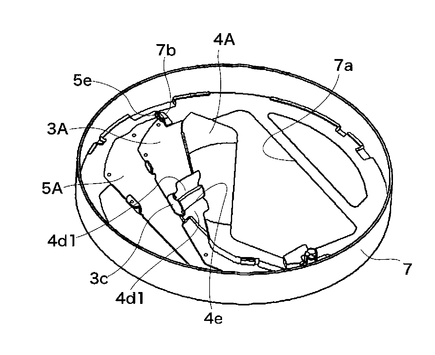
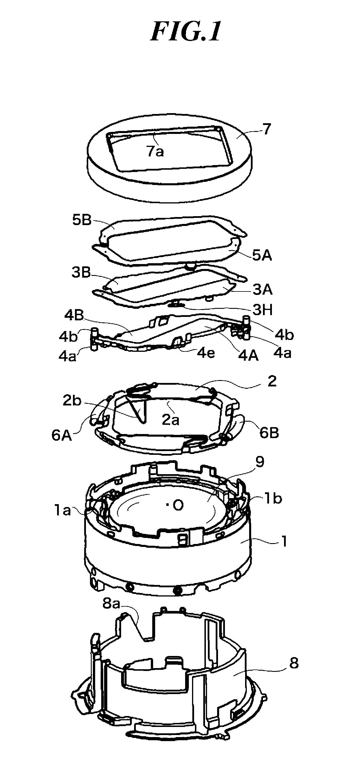
[0035]FIG. 1 shows in exploded perspective view a barrier device according to one embodiment of this invention, and FIG. 13 shows in external perspective view an example image pickup apparatus that can be mounted with the barrier device. The following is a description of a compact digital camera that serves as the image pickup apparatus.

[0036]As shown in FIG. 13, the compact digital camera 100 has a camera body 101 mounted with a retractable lens barrel 110 on which the barrier device of this embodiment is mounted. On the camera body 101, there are disposed a main switch 102, photographing switch 103, and zoom lever 107.

[0037]The main switch 102 is for turning on / off power supply to the camera. The photographing switch 103 is half-pressed to perform a preparatory operation for photographing such as light measurement and distance measurement, and ful...


PUM


Abstract

A barrier device in which excessive relative displacements of barrier blades in an optical axis direction are restricted to ensure a normal opening and closing operation of the barrier blades. The barrier device has second, first, and third barrier blades disposed in this order in the optical axis direction. Restriction portions of the first barrier blades have through portions extending from shielding portions in the optical axis direction and extending through elongated holes of the second barrier blades, and have extension portions extending parallel to the shielding portions from image-plane-side ends of the through portions and positioned on the image plane side of the second barrier blades. During the entire stroke of opening and closing of the barrier blades, the extension portions can be engaged with the shielding portions, whereby the second barrier blades are restricted from moving away from the first barrier blades.

Description

BACKGROUND OF THE INVENTION[0001]1. Field of the Invention[0002]The present invention relates to a barrier device for opening and closing a front surface of an optical lens of optical equipment to protect the optical lens not in use, and relates to an image pickup apparatus having the barrier device.[0003]2. Description of the Related Art[0004]Conventionally, a barrier device for covering a front surface of an optical lens of optical equipment to protect the optical lens has been known and widely used for image pickup apparatuses such as a camera having a motor-driven retractable barrel.[0005]Japanese Laid-open Utility Model Publication No. H3-18519 discloses an image pickup apparatus including a barrier device having barrier blades that are opened and closed to prevent a surface of an optical lens from being adhered with dust and stain and from being scratched (hereinafter, referred to as the first conventional barrier device). FIGS. 14 and 15 respectively show a fully closed state...

Claims


Application Information

Patent Timeline
Patent Type & Authority Patents(United States)
IPC IPC(8): G03B9/10
CPCG03B11/043H04N5/2254G03B17/04H04N23/55
Inventor MIYOSHI, KAORITERADA, SHUICHI
Owner CANON KK
Features
  • R&D
  • Intellectual Property
  • Life Sciences
  • Materials
  • Tech Scout
  • Unparalleled Data Quality
  • Higher Quality Content
  • 60% Fewer Hallucinations
Learn More