Breather device

a technology of breather and breech, which is applied in the direction of valve housing, electrical apparatus casing/cabinet/drawer, casing/cabinet/drawer details, etc., can solve the problem of water entering the casing, the pressure difference at which air is exhausted becomes stronger, and it is more difficult to resolve the pressure in the internal space of the casing, so as to achieve the effect of reducing the size of the casing and reducing the pressure difference required to tak

Inactive Publication Date: 2021-09-02
TOYOTA JIDOSHA KK
View PDF0 Cites 0 Cited by
  • Summary
  • Abstract
  • Description
  • Claims
  • Application Information

AI Technical Summary

Benefits of technology

[0016]The valve is brought into the closed valve state with the valve element pushed against the seal portion with the second valve member blocking the valve hole of the first valve member. The closed valve state can be maintained when there is no pressure difference between the internal space and the external space, since the elastic force of the first spring that presses the first valve member, of the springs that are disposed at positions facing each other with the valve element interposed therebetween, is set to be larger than the elastic force of the second spring that presses the second valve member.
[0017]The first valve member is moved away from the seal portion less easily as the elastic force of the first spring in the closed valve state is stronger, for example. Therefore, the pressure difference required to take in air can be set to be larger by making the elastic force of the first spring stronger. On the other hand, the second valve member is moved away from the first valve member more easily as the elastic force of the second spring in the closed valve state is weaker. Therefore, the pressure difference required to exhaust air can be set to be smaller by making the elastic force of the second spring weaker.
[0018]That is, the closed valve state can be maintained when there is no pressure difference between the internal space and the external space since the elastic force of the first spring in the closed valve state is set to be larger than the elastic force of the second spring, and the valve-opening pressure difference that meets the demand can be set within such a range that the elastic force of the first spring is larger than the elastic force of the second spring.
[0019]With the breather device according to the aspect described above, as described above, the valve-opening pressure difference that meets the demand made for the breather device can be achieved by adjusting the elastic force of the spring without changing the pressure receiving area of the valve element. That is, it is possible to achieve the valve-opening pressure difference that meets the demand made for the breather device without increasing the size of the casing of the valve or without the valve-opening pressure difference being affected by a manufacturing error of the valve element.

Problems solved by technology

Therefore, it is not preferable for the breather device that air is taken in immediately when the pressure in the internal space becomes lower than the pressure in the external space since the case gets wet with water.
Therefore, water tends to enter the case when the pressure in the internal space is lowered since the case gets wet with water.
When the elastic force of the outside spring 562 is made stronger in order to make the elastic force of the inside spring 561 larger, the pressure difference at which air is exhausted becomes stronger, which makes it more difficult to resolve a situation in which the pressure in the internal space of the case is high.
When the valve element is reduced in size, for example, in order to reduce the pressure receiving area, meanwhile, the effect of fluctuations in the size of the valve element due to a manufacturing error on the valve-opening pressure difference tends to be large, and it is difficult to set the valve-opening pressure difference to a prescribed value.
In this manner, it has not been easy to set the pressure difference at which air is exhausted and the pressure difference at which air is taken in in accordance with the demand made for the breather device.
Therefore, even if water droplets are carried by a flow of air to enter the ventilation passage from the open port in the case where air is taken in when the pressure in the internal space of the case becomes low, the water droplets that have entered the ventilation passage inevitably collide against the inner wall of the ventilation passage, which makes it difficult for the water droplets to reach the ventilation port.
Thus, even if water droplets enter the ventilation passage, the water droplets collide against the inner wall of the ventilation passage, which makes it difficult for the water droplets to reach the ventilation port.
Thus, water droplets tend to fall before reaching the ventilation port even if water droplets enter the ventilation passage from the open port.
That is, water droplets do not easily reach the ventilation port, which suppresses entry of water into the internal space of the case during air intake.

Method used


Image

  • Breather device
  • Breather device
  • Breather device

Examples


first embodiment

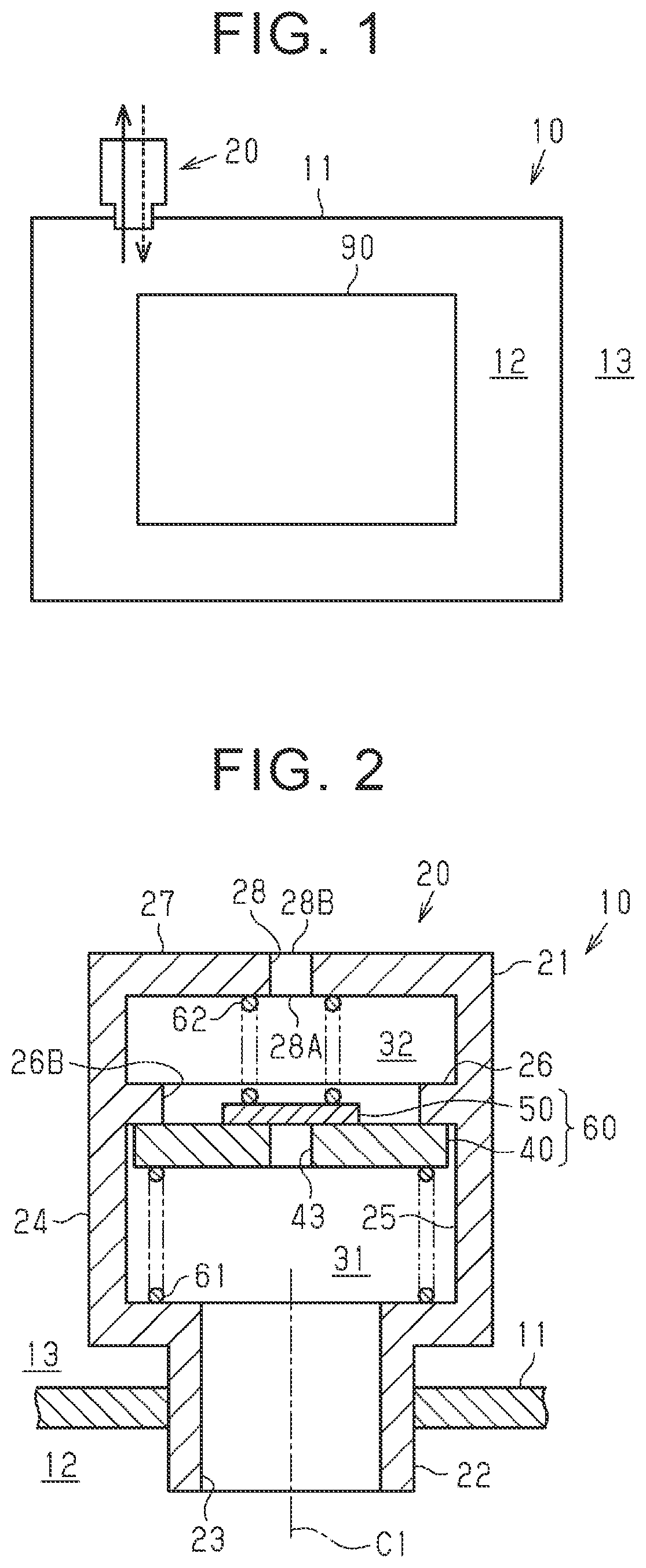
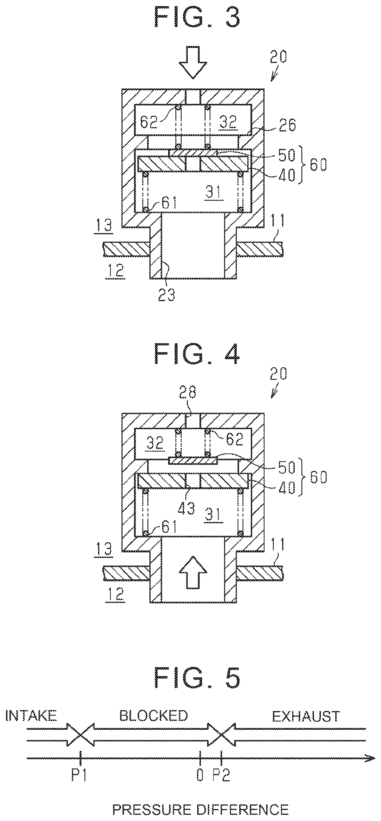
[0071]The functions of the first embodiment will be described. There is a demand for the breather device to quickly resolve a pressure difference through exhaust when the pressure in the internal space of the case becomes high. In the case where the breather device is placed in an environment in which the case may get wet with water, meanwhile, the pressure in the internal space may be lowered to be lower than the pressure in the external space when air in the case is cooled as the case gets wet with water. If the valve is opened because of the pressure difference at this time, water may enter the case. Therefore, it is not preferable for the breather device that air is taken in immediately when the pressure in the internal space becomes lower than the pressure in the external space since the case gets wet with water.

[0072]With the breather device 10, the magnitude of the intake pressure difference P1 can be set to be larger as the first spring load F1 is increased using the relatio...

second embodiment

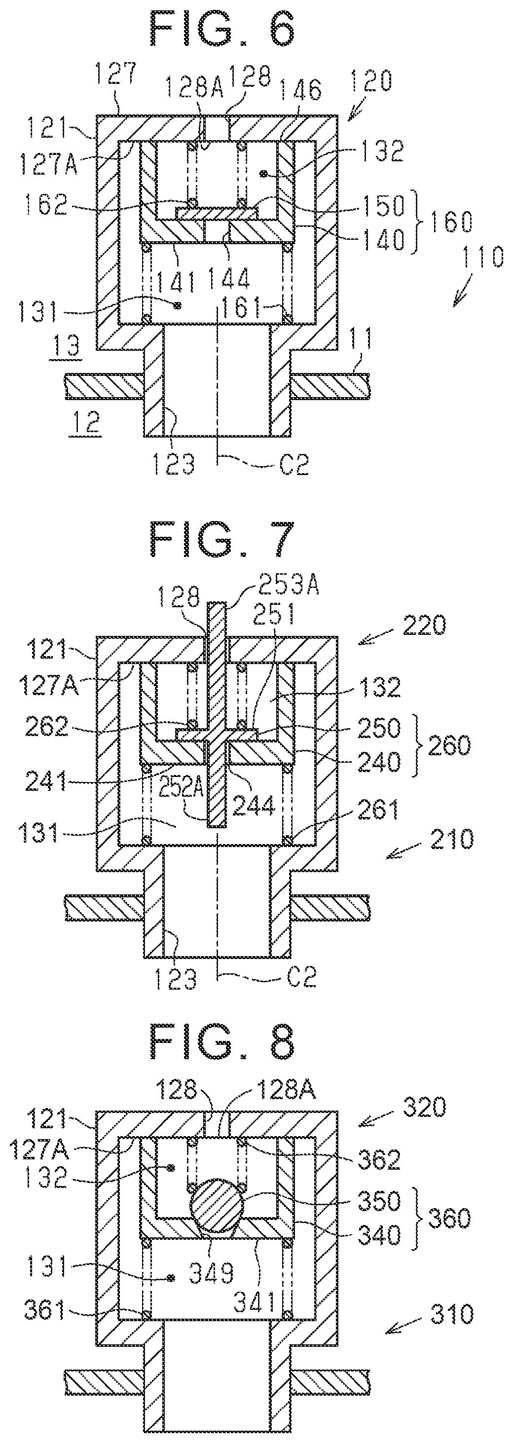
[0101]Next, a breather device according to the present disclosure will be described with reference to FIG. 9. As illustrated in FIG. 9, a breather device 410 is configured such that the valve element 160 of a valve 420 is composed of the first valve member 140 and the second valve member 150 as in the breather device 110 illustrated in FIG. 6. The valve element 160 is not described in detail.

[0102]As illustrated in FIG. 9, the breather device 410 is mounted on a vehicle with an axis C3, which extends along the central axis of a communication path 423, directed in the horizontal direction. In addition, an O-ring 71 is attached to an insertion portion 422 of a housing 421 to seal the boundary between the insertion portion 422 and a case 411.

[0103]The case 411 includes a protruding portion 414 that shields the valve 420 from the lower side in the vertical direction. Further, the breather device 410 is different from the breather device 110 in that a lid portion 429 is attached to the h...


PUM


Abstract

A breather device includes a case housing a device in an internal space and a valve tightly sealing the internal space. The valve includes a housing, a communication path, a ventilation passage, a seal portion, a valve element, and a spring. The valve element includes first and second valve members. The second valve member abuts against the first valve member to block a valve hole thereof. The spring includes first and second springs. The first spring pushes the first valve member against the seal portion in the housing of the valve. The second spring pushes the second valve member against the first valve member. The valve is brought into a closed valve state with the valve element pushed against the seal portion with the second valve member blocking the valve hole. The elastic force of the first spring in the closed valve state is larger than the second spring.

Description

CROSS-REFERENCE TO RELATED APPLICATION[0001]This application claims priority to Japanese Patent Application No. 2020-031488 filed on Feb. 27, 2020, incorporated herein by reference in its entirety.BACKGROUND1. Technical Field[0002]The present disclosure relates to a breather device that includes a case that defines a space and a valve that tightly seals the space. In the breather device, air can be taken into the case and can be exhausted from the case.2. Description of Related Art[0003]Japanese Unexamined Patent Application Publication No. 2009-106024 (JP 2009-106024 A) discloses a breather device that includes a case that houses a motor-generator in its internal space and a valve that allows air to be taken into the internal space of the case and exhausted from the internal space.[0004]FIG. 10 illustrates, as an example of a breather device according to the related art, a breather device 510 including two valve members that allow air to be taken in and exhausted, as with the breat...

Claims


Application Information

Patent Timeline
Patent Type & Authority Applications(United States)
IPC IPC(8): F16H57/027H05K5/02F16K17/196
CPCF16H57/027F16K17/196H05K5/0213F16K27/02H02K5/04
Inventor CAO, JIADONGYAMAOKA, DAISUKE
Owner TOYOTA JIDOSHA KK
Why Eureka
Try Eureka