Pressure relief device

A technology of a pressure relief device and a pressure relief plate, which is applied in the valve device, the device used to relieve pressure on the sealing surface, the device for absorbing fluid energy of the valve, etc. The problem of large difference and inconvenient opening and closing of the diaphragm can achieve the effect of preventing the pressure difference from being too large, reducing the force of the blind plate, and having a simple structure.

Inactive Publication Date: 2014-03-26
BEIJING JINGCHENGKELIN ENVIRONMENTAL PROTECTION TECH +1
View PDF4 Cites 0 Cited by
  • Summary
  • Abstract
  • Description
  • Claims
  • Application Information

AI Technical Summary

Problems solved by technology

However, the pressure difference between the front and back of the isolation device is large, which is not convenient for the opening and closing of the partition, so further improvement is urgently needed
[0003] In view of the disadvantages of large pressure difference on both sides of the partition and difficult opening and closing of the above-mentioned existing isolation devices during the opening and closing process, the designer of this technology is based on years of research, field experience and professional knowledge, combined with actual use conditions and structural technical requirements , actively improve and innovate, in order to realize a pressure relief device that can replace the existing diaphragm and realize fluid cut-off and opening under the condition of large pressure difference

Method used


Image

  • Pressure relief device

Examples


Embodiment Construction

[0013] The details of the present invention can be understood more clearly with reference to the accompanying drawings and the description of specific embodiments of the present invention. However, the specific embodiments of the present invention described here are only for the purpose of explaining the present invention, and should not be construed as limiting the present invention in any way. Under the teaching of the present invention, the skilled person can conceive any possible modification based on the present invention, and these should be regarded as belonging to the scope of the present invention.

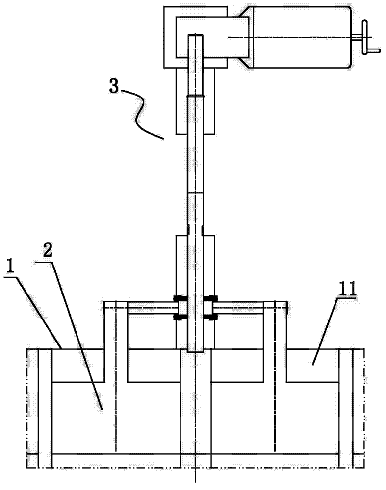
[0014] Please refer to figure 1 It is a structural schematic diagram of the pressure relief device of the present invention. Such as figure 1 As shown, the pressure relief device of the present invention is used for the opening and closing of the fluid channel. The pressure relief device includes a partition 1, a pressure relief plate 2 and a driving mechanism 3. The pa...


PUM


Abstract

The invention provides a pressure relief device. The pressure relief device comprises a movable partition plate, pressure relief plates and a driving mechanism, wherein mounting groove rabbets are formed in the partition plate along the moving direction of the partition plate; the pressure relief plates can be movably and respectively arranged in the mounting groove rabbets along the moving direction of the partition plate; the driving mechanism is connected with the pressure relief plates; the driving mechanism is used for driving the pressure relief plates to move along the moving direction of the partition plate in the mounting groove rabbets. The pressure relief plates are opened first before the partition plate is lifted, and then, the partition plate is opened. Otherwise, the partition plate is closed first, and then, the pressure relief plates are closed. As a special structure with a pressure equalizing function is adopted by the pressure relief device provided by the invention, the cutoff and opening of the partition plate can be realized under the high-pressure difference working condition.

Description

technical field [0001] The invention relates to a pressure relief device, in particular to a pressure relief device used in a large pressure difference industrial fluid piping system. Background technique [0002] In many industrial fluid piping systems, isolation devices are required. However, the pressure difference between the front and back of the isolation device is large, which is not convenient for the opening and closing of the partition, so further improvement is urgently needed. [0003] In view of the disadvantages of the above-mentioned existing isolation devices, such as large pressure difference on both sides of the partition and difficult opening and closing during the opening and closing process, the designer of this technology is based on years of research, field experience and professional knowledge, combined with actual use conditions and structural technical requirements , actively improve and innovate, in order to realize a pressure relief device that c...

Claims


Application Information

Patent Timeline
Patent Type & Authority Applications(China)
IPC IPC(8): F16K3/30F16K47/08
CPCF16K3/314F16K39/04
Inventor 杨源满井小梅杨明华王元新胡建红常海花
Owner BEIJING JINGCHENGKELIN ENVIRONMENTAL PROTECTION TECH
Why Eureka
Try Eureka