Laryngeal mask cuffs
What is Al technical title?
Al technical title is built by PatSnap Al team. It summarizes the technical point description of the patent document.
a technology of cuffs and laryngeal masks, which is applied in the direction of respirators, trachea tubes, etc., can solve the problems of increased cuff pressure, lingual, hypoglossal, recurrent laryngeal nerve palsy, etc., and achieve the effect of facilitating lung ventilation
Active Publication Date: 2020-08-18
AIRWAY MEDIX SA
View PDF35 Cites 0 Cited by
Summary
Abstract
Description
Claims
Application Information
AI Technical Summary
This helps you quickly interpret patents by identifying the three key elements:
Problems solved by technology
Method used
Benefits of technology
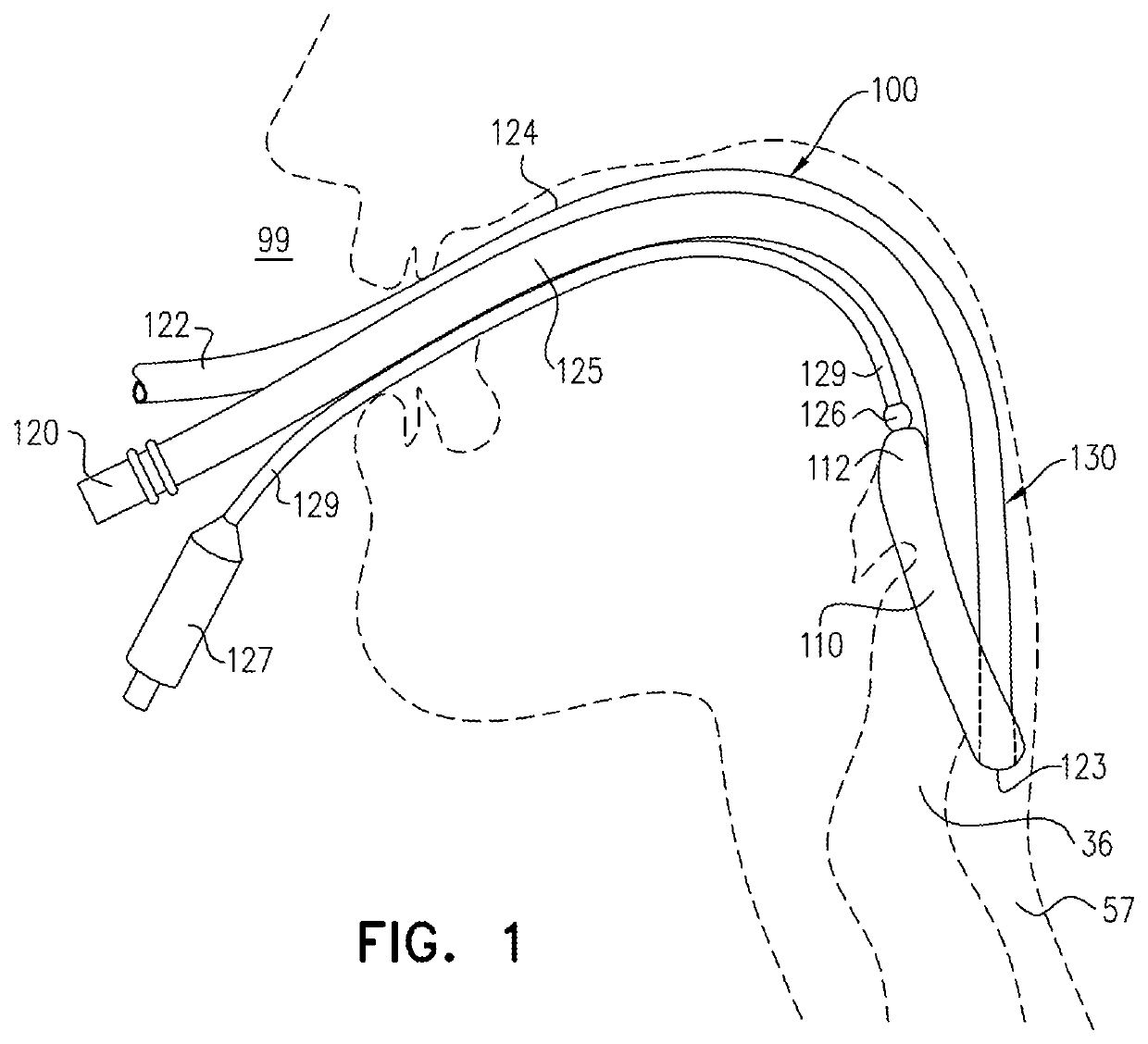
[0009]Embodiments of the present invention provide a laryngeal mask airway (LMA) device, which comprises an inflatable annular cuff that is insertable through a mouth of a patient to an LMA-insertion location within the patient, such that an anterior side of the cuff forms a seal around a laryngeal inlet of the patient and renders the LMA device suitable for facilitating lung ventilation.
Problems solved by technology
Similarly, in patients provided with a laryngeal mask, a high cuff pressure may lead to palsy of the lingual, hypoglossal, and recurrent laryngeal nerves, and postoperative sore throat.
The risk during anesthesia with nitrous oxide (NO) is further complicated by the fact that NO gases penetrate the cuff, thereby gradually increasing the cuff pressure above the initial setting at which the cuff was inflated.
Method used
Image
Click on the blue label to locate the original text in one second.
Reading with bidirectional positioning of images and text.
Examples
Embodiment Construction
[0175]FIG. 1 is a schematic illustration of a laryngeal mask airway (LMA) device 100, in accordance with an application of the present invention. In typical use, LMA device 100 is inserted into the throat while deflated (the upper surface of the throat is bounded by hard and soft palates). LMA device 100 is lodged in the pharynx at the base of the hypopharynx where the throat divides into the trachea 36 and the esophagus 57. For some applications, after LMA device 100 is thus lodged in the pharynx, an inflatable annular cuff 110 defined by an inflatable balloon 112 of LMA device 100 is inflated at the LMA-insertion location with the patient, as illustrated in FIG. 1.
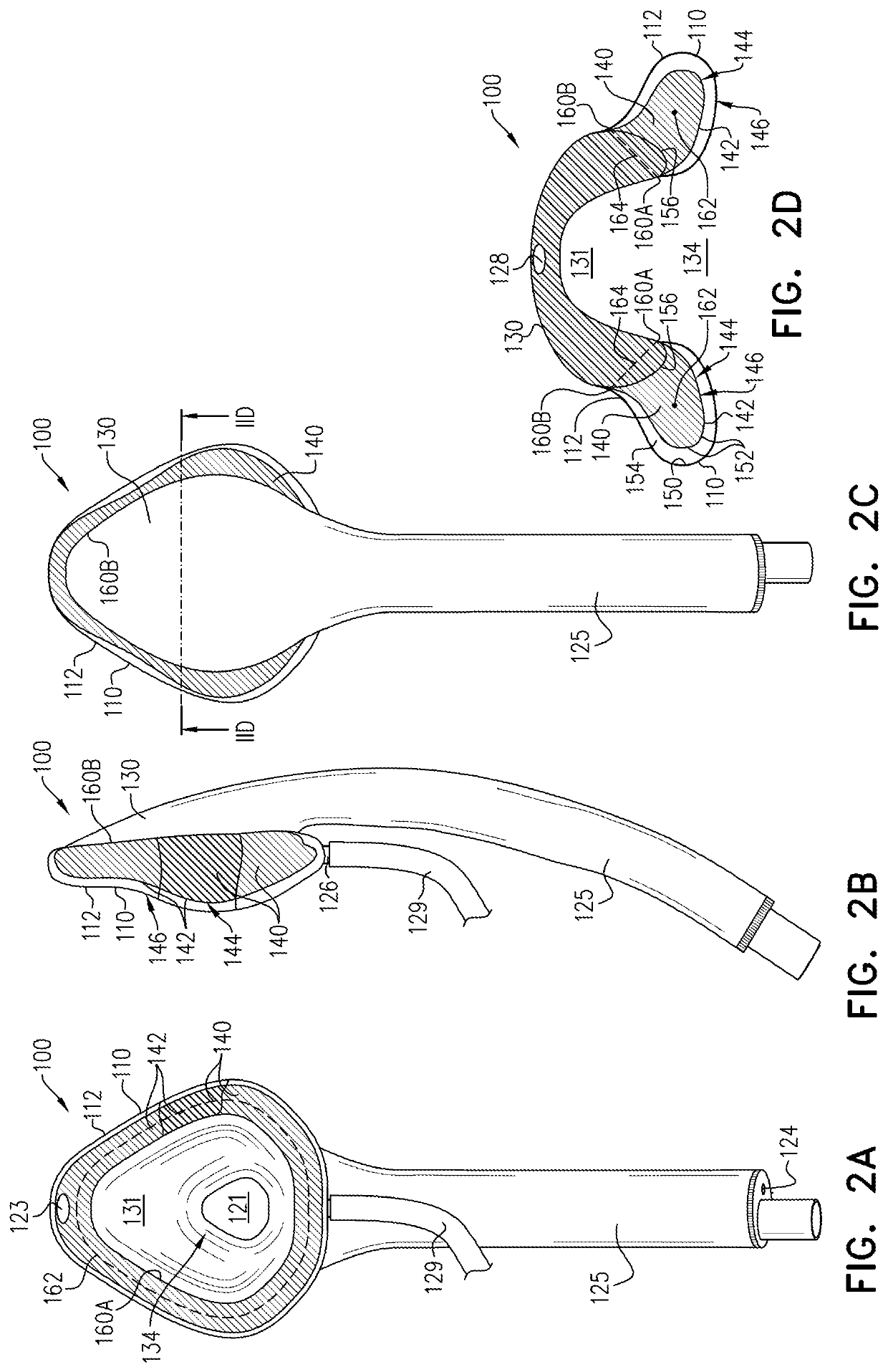
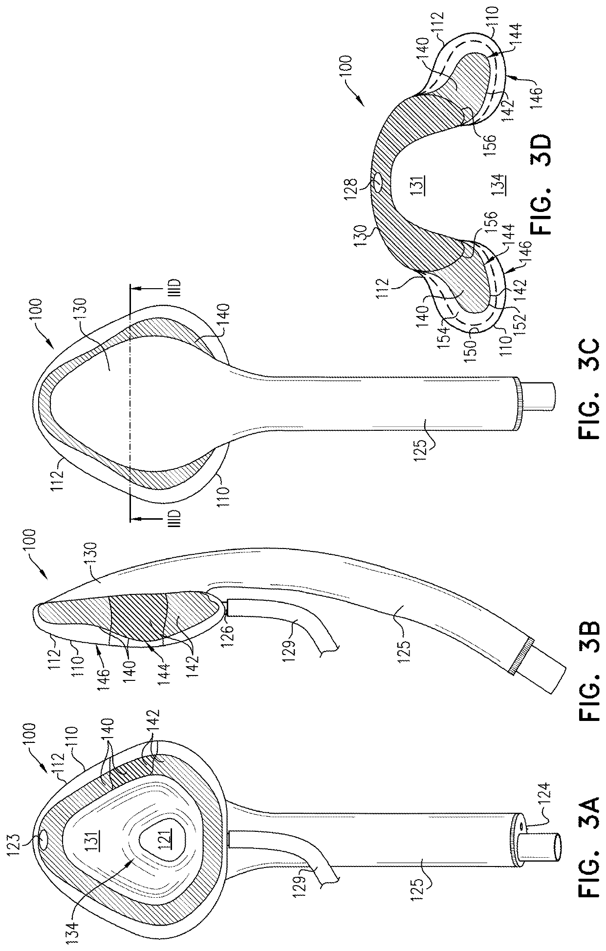
[0176]Reference is still made to FIG. 1 and is additionally made to FIGS. 2A-D and 3A-D, which are schematic illustrations of respective views of LMA device 100 with inflatable annular cuff 110 inflated at a low pressure and a working medium pressure PM, respectively, in accordance with an application of the present inve...
PUM
Abstract
A laryngeal mask airway (LMA) device includes a backplate, an inflatable balloon, an airway tube, and a non-inflatable skeleton, which extends anteriorly from the backplate, and which is shaped so as to define a skeleton anterior side that has a pre-formed shape. A distal end of an inflation tube is coupled in fluid communication with (i) an interior of the inflatable balloon for supplying air to the inflatable balloon, and (ii) at least a portion of the skeleton anterior side. The inflatable balloon is shaped so as to define an inflatable annular cuff which (a) covers at least a portion of the skeleton anterior side, and (b) has a cuff anterior side that is configured to form a seal around a laryngeal inlet of a patient when the inflatable annular cuff is disposed at an LMA-insertion location within a throat of the patient. Other embodiments are also described.
Description
CROSS-REFERENCE TO RELATED APPLICATIONS[0001]The present application is a continuation of International Application PCT / IL2019 / 050405, filed Apr. 11, 2019, which (a) claims priority from U.S. Provisional Application 62 / 789,208, filed Jan. 7, 2019, and (b) claims priority from and is a continuation-in-part of International Application PCT / IL2018 / 051306, filed Nov. 29, 2018, which (i) claims priority from and is a continuation-in-part of U.S. application Ser. No. 15 / 951,564, filed Apr. 12, 2018, now U.S. Pat. No. 10,173,022, and (ii) claims priority from and is a continuation-in-part of U.S. application Ser. No. 15 / 878,993, filed Jan. 24, 2018, now U.S. Pat. No. 10,369,311, which claims the benefit of U.S. Provisional Application 62 / 592,020, filed Nov. 29, 2017. All of these applications are assigned to the assignee of the present application and are incorporated herein by reference.FIELD OF THE APPLICATION[0002]The present invention relates generally to lung ventilation devices, and ...
Claims
Application Information
Patent Timeline
Application Date:The date an application was filed.
Publication Date:The date a patent or application was officially published.
First Publication Date:The earliest publication date of a patent with the same application number.
Issue Date:Publication date of the patent grant document.
PCT Entry Date:The Entry date of PCT National Phase.
Estimated Expiry Date:The statutory expiry date of a patent right according to the Patent Law, and it is the longest term of protection that the patent right can achieve without the termination of the patent right due to other reasons(Term extension factor has been taken into account ).
Invalid Date:Actual expiry date is based on effective date or publication date of legal transaction data of invalid patent.