

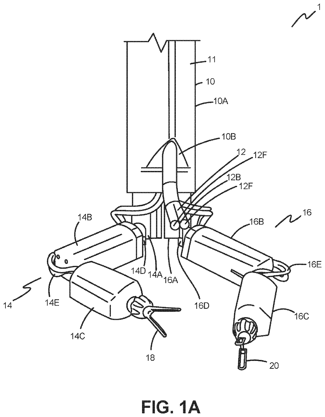
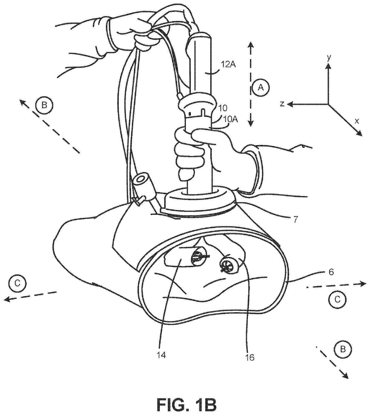
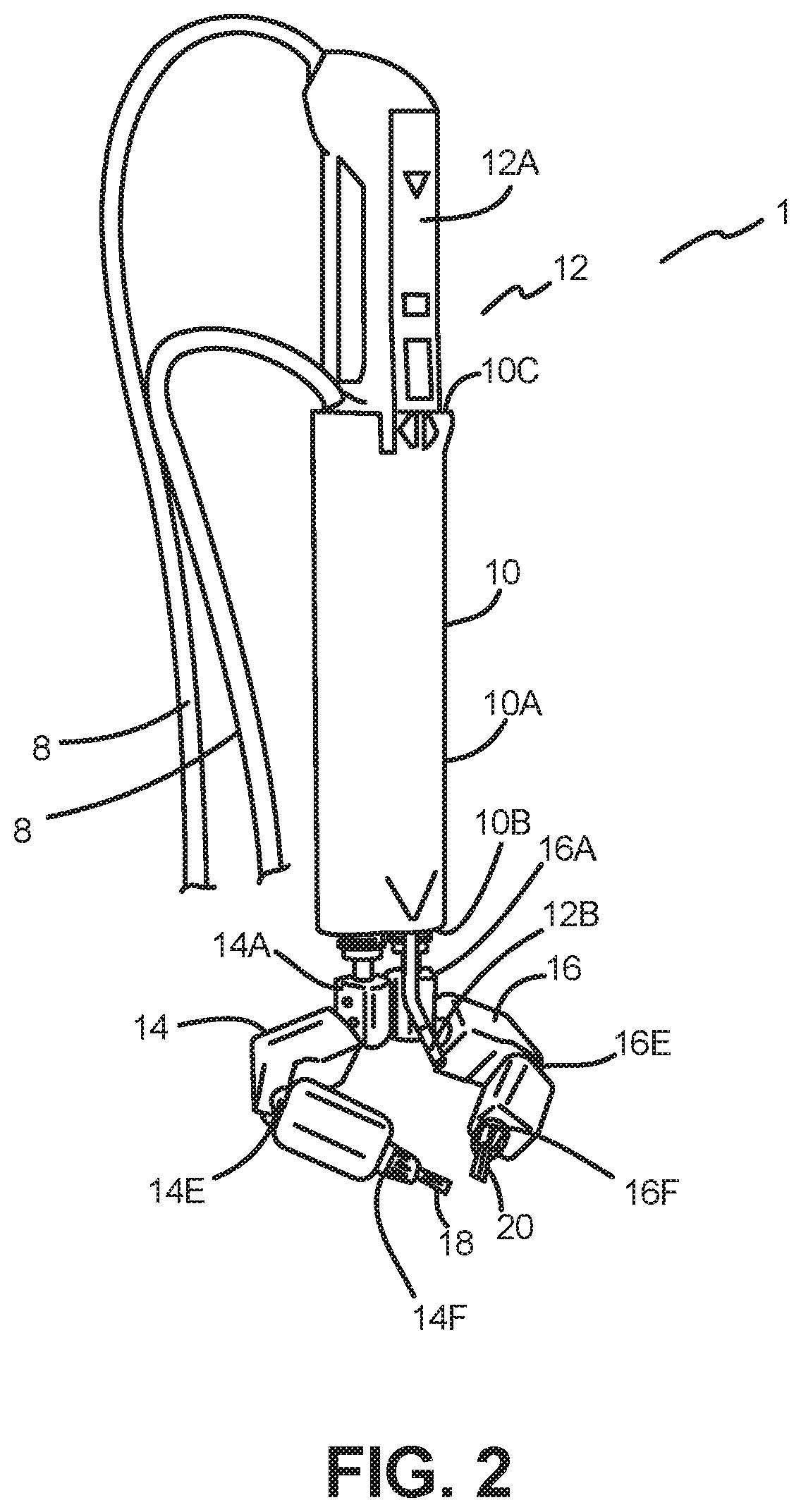
Robotic surgical devices, systems and related methods
a robotic surgery and robotic technology, applied in the field of medical devices, can solve the problems of limited scope and complexity of known minimally invasive technologies such as laparoscopy, large size, and high cost, and achieve the effects of reducing the number of surgical instruments, and reducing the number of surgical operations
- Summary
- Abstract
- Description
- Claims
- Application Information
AI Technical Summary
Benefits of technology
Problems solved by technology
Method used
Image

Examples
embodiment 500
[0233]FIG. 52 depicts another support embodiment 500 having a track 502 along which the robotic device 10 can move in a similar fashion to the carriage embodiments discussed above. It is understood that the track 502 can have any of the features described above with respect to other track embodiments. A handle 504 is coupled to one end of the track 502 and can slide the track 502 translationally or rotate the track 502. More specifically, the handle 504 has an inner component 504B and an outer component 504A that is slideable in relation to the inner component 504B. Further, the handle 504 is coupled to the track 502 such that when the outer component 504A is slid in relation to the inner component 504B, the outer component 504A moves the track 502 in the same translational direction as indicated by arrow T. For example, when the outer component 504A is urged distally toward the surgical space (represented by the sphere S), the track 502 is also urged toward the surgical space in th...
embodiment 520
[0234]A further support embodiment 520 is depicted in FIG. 52B. In this embodiment, the support 520 has two tracks 522, 524 that are coupled or “in parallel.” That is, the support 520 has a single carriage 526 that is coupled to both the first and second tracks 522, 524, thereby resulting in coupled movement of the carriage 526 in relation to the two tracks 522, 524. It is understood that the two tracks 522, 524 can be structured in a similar fashion to and have similar features to the previous track embodiments discussed above. Further, the carriage 526 can be similar to the previously described carriage embodiments, except with respect to the fact that the instant carriage 526 is directly coupled to both of the tracks 522, 524 as depicted. That is, in this implementation, the carriage 526 has two portions (or segments): a top or first portion 526A that is moveably coupled to the second track 524 and a bottom or second portion 526B that is moveably coupled to the first track 522.
[0...
PUM
 Abstract
Description
Claims
Application Information