
Cannula with lateral access and directional exit port

Active Publication Date: 2009-04-23
MITCHELL DAVID
View PDF48 Cites 47 Cited by
  • Summary
  • Abstract
  • Description
  • Claims
  • Application Information

AI Technical Summary

Benefits of technology

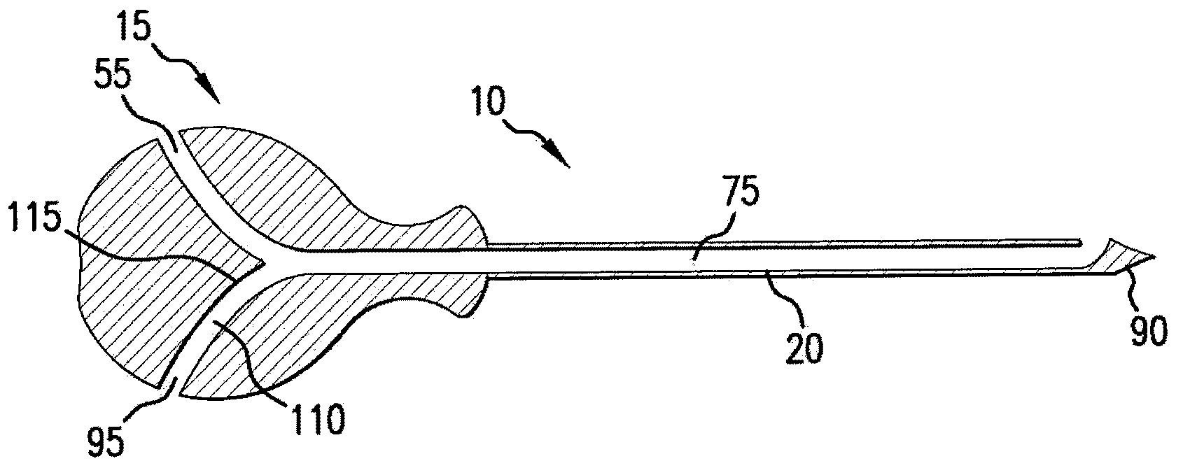
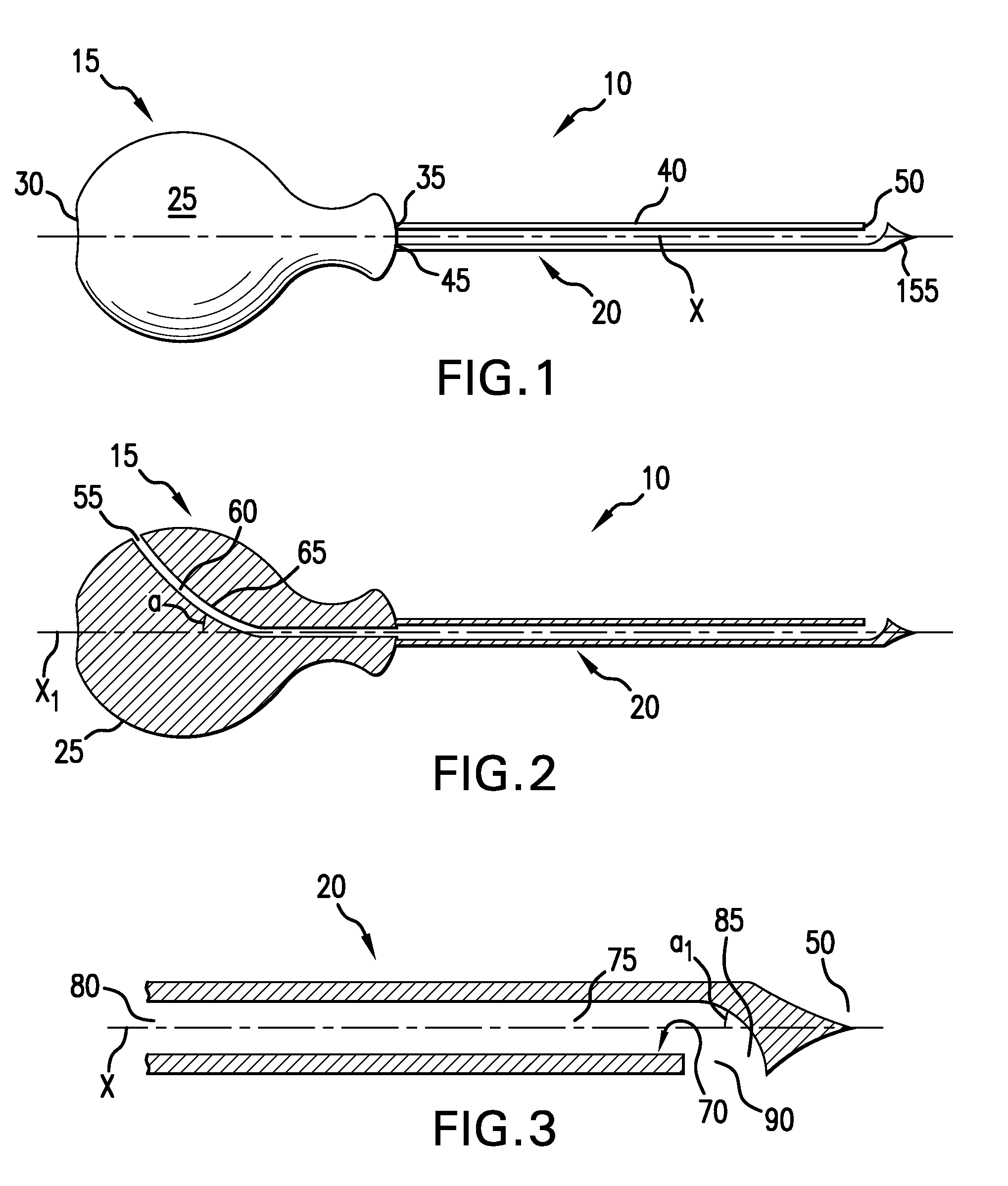
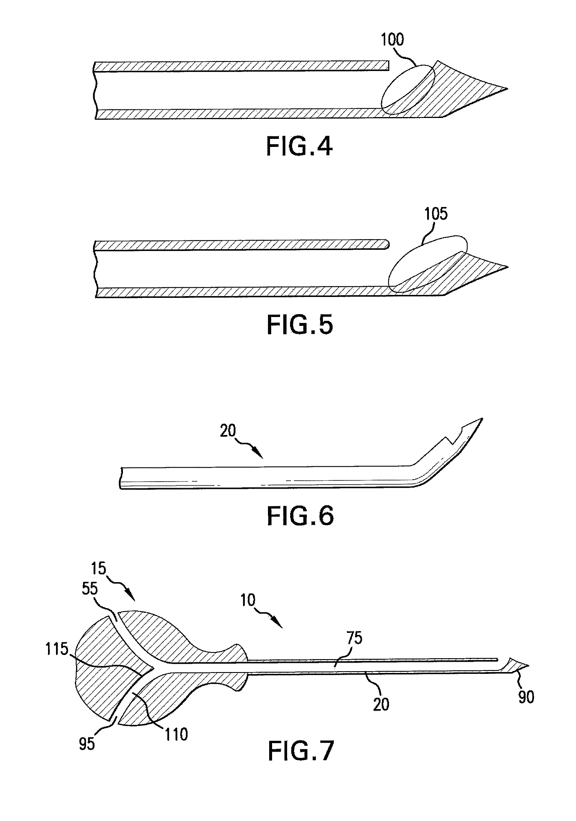
[0005]In an embodiment, the present invention provides a cannula system that allows for directional placement of an orthopedic tool as well as a side entry port that provides a user with more maneuverability in handling the orthopedic tool during a surgical procedure. A cannula of a cannula system of the present invention generally comprises a handle and a cannula shaft. The handle comprises a handle body having a proximal portion and a distal portion. The cannula shaft comprises an elongate tubular body having a proximal end depending from the distal portion of the handle body, a distal end terminating in a pointed tip, and a longitudinal axis extending therethrough. The handle further comprises a first side entry port in fluid communication with a first lumen that has at least a partial section that is curved or angled with respect to an imaginary center line that extends through the handle body. The imaginary center line is also aligned with the longitudinal axis of the cannula shaft. The cannula shaft further has an inner wall defining a channel that has a proximal end and a distal end. The proximal end of the channel is in fluid communication with the first lumen of the handle body and the distal end of the channel is in fluid communication with a side distal exit port. The distal end of the channel is also spaced apart from the distal end of the elongate body. The inner wall is configured to lateral deflect the channel at the channel's distal end with respect to the longitudinal axis of the elongate body to transition the channel's distal end to the side distal exit port.

Problems solved by technology

For example, bone fractures are a very common orthopedic problem that can occur because of a number of factors, such as injury, disease or progressive age.
Many of the orthopedic tools used in these procedures and other orthopedic procedures involve complex, high profile components.
In addition, many are not completely controllable by the user.
Therefore, the dimensions of a balloon created cavity are largely beyond the control of the user and more or less dependent upon the extent of disruption of the architecture of the pathologic bone.
Furthermore, a problem associated with current orthopedic tool placement systems used in many of these procedures is that they do not accommodate the vertical height limitations present in the operating room during the procedure.
For example, because of the fluoroscopic imaging devices that are above the orthopedic tool placement systems, a user has limited vertical space to maneuver instruments through the tool placement systems.

Method used


Image

  • Cannula with lateral access and directional exit port
  • Cannula with lateral access and directional exit port
  • Cannula with lateral access and directional exit port

Examples


Embodiment Construction

[0035]As used herein, the terms “side,”“top” and “down” are described with respect to the cannula system as seen from a top plan view (such as shown in FIG. 1).

[0036]In general, the present invention provides a cannula system that is readily maneuverable in an operating room setting, can be used to expose different instrumentalities to a target site, and has directional capabilities to allow the user to treat multiple quadrants or areas of a target site. Since the cannula system has particular application in the orthopedic setting, the target site is often bone.

[0037]Specifically, referring to FIG. 1, in an embodiment, the present invention provides a cannula system that includes a cannula 10 comprising a handle 15 and a cannula shaft 20. Handle 15 comprises a handle body 25 having a proximal portion 30 and a distal portion 35. Cannula shaft 20 comprises an elongate tubular body 40 having a proximal end 45 and a distal end 50. Proximal end 45 depends from distal portion 35 of handle...


PUM


Abstract

The present invention generally provides a cannula system that is readily maneuverable in an operating room setting, can be used to expose different instrumentalities to a target site, and has directional capabilities to allow the user to treat multiple quadrants or areas of a target site. The present invention provides cannula systems including these different instrumentalities as well as methods of operating these cannula systems and methods of treating orthopedic conditions using these cannula systems.

Description

BACKGROUND OF THE INVENTION[0001]There are many different orthopedic conditions that require surgical intervention. For example, bone fractures are a very common orthopedic problem that can occur because of a number of factors, such as injury, disease or progressive age. One type of surgical procedure used to treat fractures of the spine is vertebroplasty. Vertebroplasty involves injecting liquid bone cement into the interstices of the weakened bone under pressure. The bone cement subsequently hardens to fix the vertebral body. Another process is kyphoplasty, in which a mechanical bone tamping device is used to elevate the vertebral body. An orthopedic cement is then injected into the space created by the bone tamp. Specifically, a bone tamping device, such as a balloon, can be placed into the intervertebral body and inflated so that a cavity is formed in the weakened bone. This cavity can then be filled with a more viscous form of bone cement.[0002]Another type of orthopedic condit...

Claims


Application Information

Patent Timeline
IPC IPC(8): A61B17/56
CPCA61B10/0233A61B17/1757A61B17/3472A61B17/885A61B17/88A61B2017/3445A61B2017/3449A61B2018/1425A61B18/1477
Inventor MITCHELL, DAVID
Owner MITCHELL DAVID
Learn More