Head holding mechanism and inkjet printer

a technology of holding mechanism and inkjet printer, which is applied in the direction of printing mechanism, power drive mechanism, printing, etc., can solve the problem of complex and achieve the effect of simplifying the replacement task of inkjet head

Active Publication Date: 2020-11-24
MIMAKI ENG
View PDF2 Cites 0 Cited by
  • Summary
  • Abstract
  • Description
  • Claims
  • Application Information

AI Technical Summary

Benefits of technology

[0008]The present disclosure thus provides a head holding mechanism that holds an inkjet head mounted on a carriage, where the head holding mechanism can simplify a replacement operation of the inkjet head. The present disclosure also provides an inkjet printer equipped with such a head holding mechanism.
[0011]Therefore, in the present disclosure, the fixing member at the engagement position is moved to the disengagement position, the head holding member in a state where an inkjet head before replacement is attached is detached from the carriage side member, and thereafter the head holding member in a state where an inkjet head after replacement is attached is set at a predetermined position of the carriage side member, and the fixing member at the disengagement position is moved to the engagement position to replace the inkjet head. That is, in the present disclosure, the inkjet head can be replaced without using a tool such as a driver or without detaching the fixing member. Therefore, according to the present disclosure, the replacement task of the inkjet head can be simplified. Furthermore, in the present disclosure, since the inkjet head can be replaced without detaching the fixing member, the fixing member can be prevented from getting lost at the time of replacing the inkjet head.
[0013]In the present disclosure, the fixing member is preferably movably held by the carriage side member and engages with the head holding member at the engagement position. According to such a configuration, the fixing member does not need to be attached to each of the head holding members detached from the carriage side member together with the inkjet head. Therefore, the configuration of the member to be replaced together with the inkjet head can be simplified.
[0019]The head holding mechanism of the present disclosure includes an inkjet head and a carriage, and can be used for an inkjet printer that performs printing on a medium. In this inkjet printer, the replacement task of the inkjet head can be simplified.
[0020]As described above, in the head holding mechanism and the inkjet printer of the present disclosure, the replacement task of the inkjet head can be simplified.

Problems solved by technology

Thus, in such an inkjet printer, a tool such as a driver is required when replacing the inkjet head mounted on the carriage, and the replacement task of the inkjet head becomes complex.

Method used


Image

  • Head holding mechanism and inkjet printer
  • Head holding mechanism and inkjet printer
  • Head holding mechanism and inkjet printer

Examples


first embodiment

[0034](Schematic Configuration of Inkjet Printer)

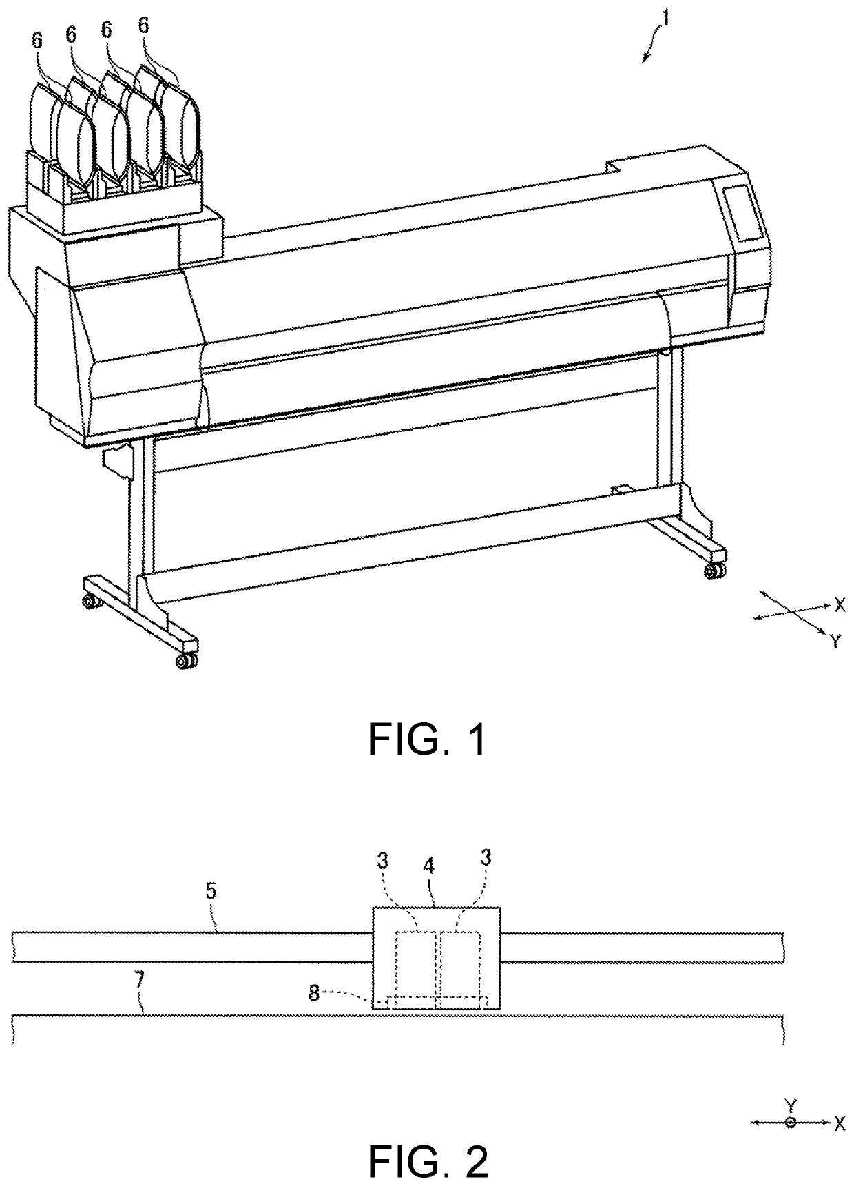
[0035]FIG. 1 is a perspective view of an inkjet printer 1 according to an embodiment of the present disclosure. FIG. 2 is a schematic view showing a carriage 4 and the like of the inkjet printer 1 shown in FIG. 1.

[0036]An inkjet printer 1 (hereinafter referred to as “printer 1”) of the present embodiment is a business inkjet printer, and performs printing on a medium such as paper or cloth. The printer 1 includes an inkjet head 3 (hereinafter referred to as a “head 3”) that ejects ink droplets toward a medium, a carriage 4 on which the head 3 is mounted, a carriage driving mechanism (not shown) that moves the carriage 4 in a main scanning direction (X direction in FIG. 1, etc.), a guide rail 5 that guides the carriage 4 in the main scanning direction, and a plurality of ink tanks 6 in which ink to be supplied to the head 3 is stored.

[0037]The head 3 ejects ink droplets downward. A platen 7 is disposed on the lower side of the head 3. ...

second embodiment

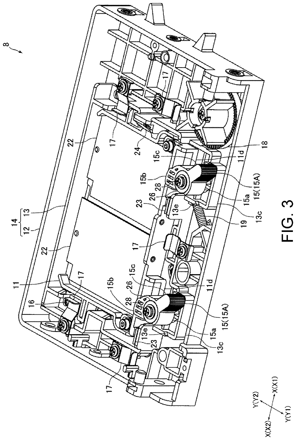
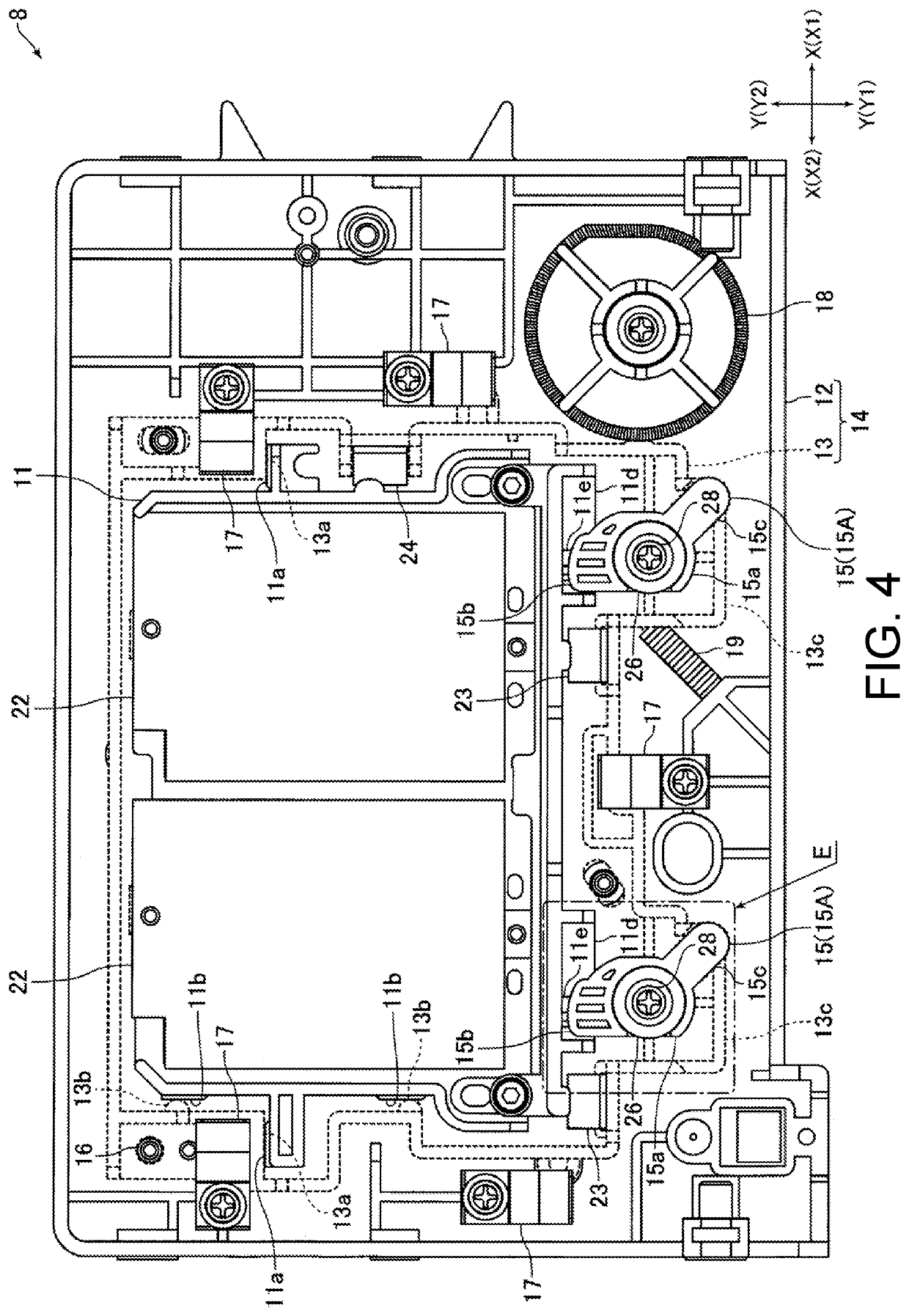
[0068]FIG. 9 is a perspective view of a head holding mechanism 8 according to a second embodiment of the present disclosure. FIG. 10 is a plan view of the head holding mechanism 8 shown in FIG. 9.

[0069]The head holding mechanism 8 according to the first embodiment includes one intermediate member 13 movably attached to the base member 12 and one head holding member 11 fixed to the intermediate member 13, where the one head holding member 11 holds two heads 3. On the other hand, the head holding mechanism 8 according to the second embodiment includes one intermediate member 43 movably attached to the base member 12, one head holding member 41 that holds one head 3 and is fixed to the intermediate member 43, and one head holding member 42 that holds one head 3 and is fixed to the base member 12. Furthermore, the fixing lever 15 for fixing the head holding member 41 to the intermediate member 43 is turnably held by the intermediate member 43, and the fixing lever 15 for fixing the head...


PUM


Abstract

A head holding mechanism and an inkjet printer are provided. The head holding mechanism includes a head holding member that holds an inkjet head, a carriage side member attached to the carriage and to which the head holding member is fixed, and a fixing member for fixing the head holding member to the carriage side member. The fixing member is movably held by the carriage side member. The fixing member is movable between an engagement position where the fixing member engages with the head holding member to fix the head holding member to the carriage side member, and a disengagement position where the engagement state of the head holding member and the fixing member is released and the head holding member is detachable from the carriage side member.

Description

CROSS REFERENCE TO RELATED APPLICATIONS[0001]This application claims the priority benefit of Japanese Patent Application No. 2018-086862, filed on Apr. 27, 2018. The entirety of the above-mentioned patent application is hereby incorporated by reference herein and made a part of this specification.TECHNICAL FIELD[0002]The present disclosure relates to a head holding mechanism that holds an inkjet head mounted on a carriage. The present disclosure also relates to an inkjet printer equipped with such a head holding mechanism.DESCRIPTION OF THE BACKGROUND ART[0003]An inkjet printer that performs printing by ejecting ink onto a medium is conventionally known (see e.g., Japanese Unexamined Patent Publication No. 2016-215421). The inkjet printer described in Japanese Unexamined Patent Publication No. 2016-215421 includes a plurality of inkjet heads (liquid ejection heads) for ejecting ink supplied from an ink container and a carriage on which the plurality of inkjet heads are mounted. The ...

Claims


Application Information

Patent Timeline
Patent Type & Authority Patents(United States)
IPC IPC(8): B41J2/14B41J25/34
CPCB41J2/14B41J25/34B41J2/14024
Inventor KOBAYASHI, HIROSHI
Owner MIMAKI ENG
Why Eureka
Try Eureka