
Combined floating-type damper brake

A brake pad, floating technology, applied in the direction of friction linings, mechanical equipment, etc., can solve the problems of reducing elastic performance, reducing vehicle weight, increasing manufacturing costs, etc., reducing manufacturing and maintenance costs, and simplifying the replacement operation process. , the effect of reducing the difficulty of manufacturing

Active Publication Date: 2013-04-24
DALIAN JIAOTONG UNIVERSITY
View PDF1 Cites 0 Cited by
  • Summary
  • Abstract
  • Description
  • Claims
  • Application Information

AI Technical Summary

Problems solved by technology

In order to solve this problem in recent years, some researches and improvements have been carried out at home and abroad; the patent number of which is 201010520153.0 through patent retrieval is a train brake pad with an adjuster. Three or three integral multiples of cricket cups are installed, that is, three brake blocks are hinged on the supporting plate as a group of multiple adjusted brake block groups, although the brake pads and brake pads have been improved to a certain extent. The effective area between the moving discs and its heat dissipation capacity, but the structure of the above-mentioned brake pads is very complicated, the processing accuracy of the parts is high, and it is not easy to install, manufacture and maintain, resulting in a greatly increased manufacturing cost; After market research, it is also found that foreign countries have made some improvements to brake pads. Most of them adjust the contact area by adding spherical mechanisms and elastic gaskets on the bottom plate of the brake pads to reduce hot spots, thereby achieving improvement. The purpose of braking force and improving the life of the friction pair
However, another problem brought by this method is that the complexity of the brake pad bottom plate mechanism is greatly increased, the manufacturing cost is significantly increased, and the weight of the brake pad is increased, which is unfavorable for reducing the weight of the vehicle
At the same time, limited by the space, the adjustable distance of the elastic gasket and spring is limited, and under high-speed braking conditions, the brake pad is in a high temperature state, and the elastic gasket and spring are easily softened due to high temperature and the elastic performance is reduced. The effect of this mechanism is greatly reduced

Method used


Image

  • Combined floating-type damper brake
  • Combined floating-type damper brake
  • Combined floating-type damper brake

Examples


Embodiment Construction

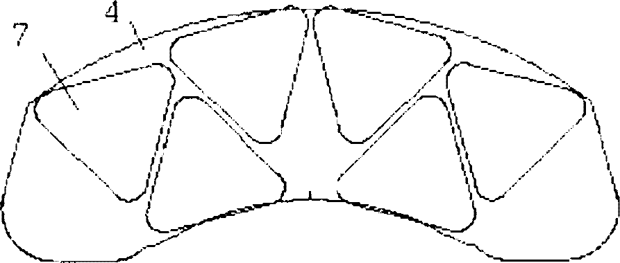
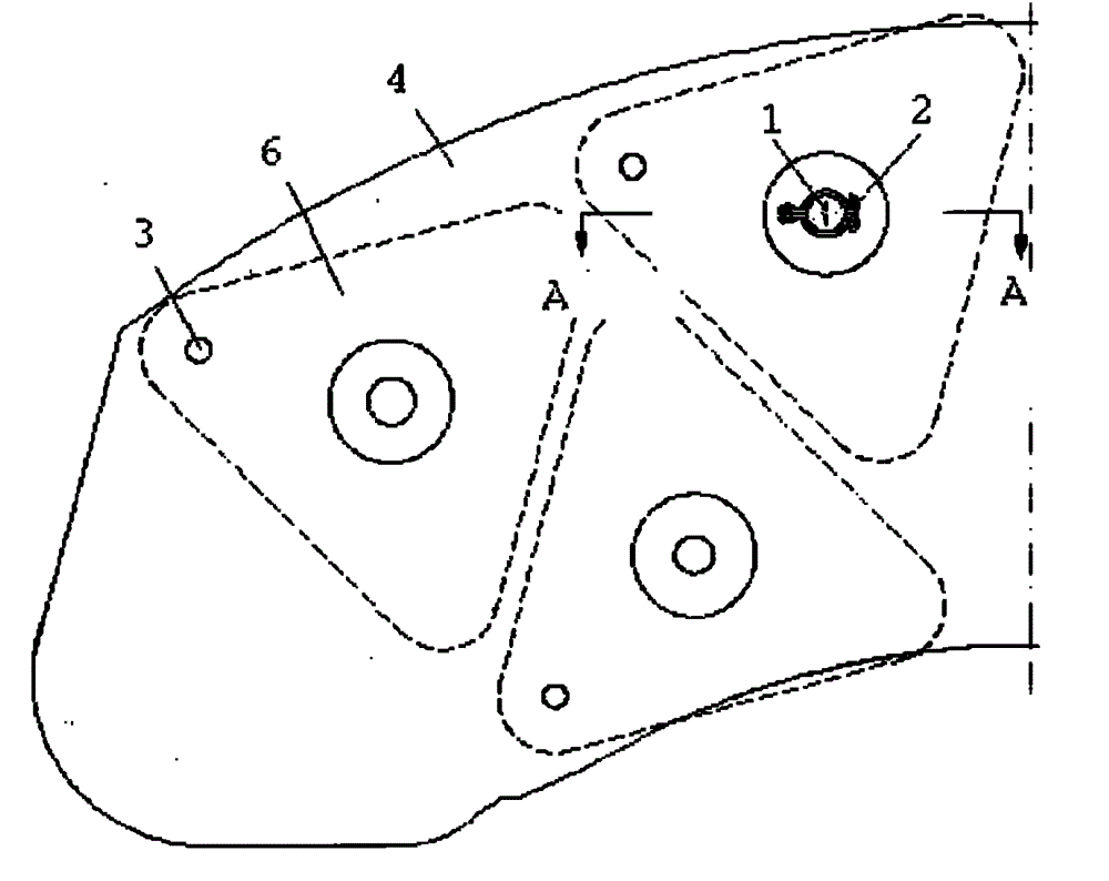
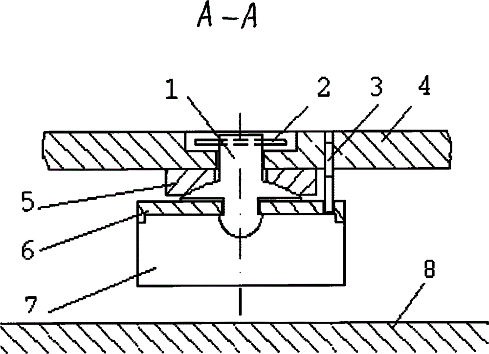
[0018] figure 1 , 2 , 3 and 4 show specific embodiments of the present invention; it is a combined floating brake pad installed on the disc brake of a high-speed train; The brake pads are characterized in that each of the brake pads adopts a combined floating brake pad, and each of the combined floating brake pads is symmetrically arranged and distributed on the supporting plate 4. A floating triangular brake block assembly that rubs against the brake disc 8, each floating triangular brake block assembly is composed of an isosceles triangle brake block 7, a bottom plate 4, a convex seat 1, a concave seat 5, The connecting rod 3 and the pin 2 are composed of an isosceles triangle brake block 7 and the bottom plate 6 are sintered to form an integrated friction block, and the bottom end of the convex seat 1 passes through the bottom plate 6 and is fixed on the bottom plate 6 by riveting; On the convex spherical surface of this convex seat 1, a concave spherical concave seat 5 coo...


PUM


Abstract

The invention belongs to brakes, and in particular relates to a combined floating-type damper brake suitable for a railway vehicle disc brake. The brake is characterized in that a combined floating-type damper brake is adopted for each damper brake, wherein six floating triangle brake block assemblies which are frictional with a brake plate are symmetrically arrayed and distributed on a support plate; and each floating triangle brake block assembly consists of a triangle brake block, a base plate, a convex surface seat, a concave surface seat, a connecting rod and a pin. The brake provided bythe invention is reasonable in design, and is simple and practical in structure, because the brake block is connected with the brake support plate directly, the brake is easy to manufacture, dismounting and replace; not only is the manufacturing difficulty reduced obviously, but also the use reliability of the damper brake is increased; the replacement operation process of the damper brake is simplified, and the manufacturing and maintaining costs are lowered; and not only is the hot mark phenomenon reduced, but also the service life of a friction pair is prolonged, and the brake is convenient to use and the like.

Description

technical field [0001] The invention belongs to brakes, in particular to a combined floating brake pad suitable for disc brakes of railway vehicles. Background technique [0002] As we all know, the brake pad is an important part of the brake, which is widely used in transportation tools such as railway vehicles, automobiles, motorcycles, and airplanes, as well as sports machinery such as oil drilling and wind power generation. In braking, the friction pair formed by the friction brake parts consumes the energy of the moving vehicle or equipment through mutual friction, so as to achieve the purpose of stopping the moving vehicle and equipment. With the improvement of the kinetic energy of moving vehicles and equipment, the conditions of use of friction brake components are becoming more and more stringent, especially in the field of high-speed train manufacturing, brake friction pairs need to be realized under high temperature and high speed conditions. Therefore, the worki...

Claims


Application Information

Patent Timeline
Patent Type & Authority Patents(China)
IPC IPC(8): F16D69/00F16D69/04
Inventor 高飞
Owner DALIAN JIAOTONG UNIVERSITY
Learn More