Eureka AIR delivers breakthrough ideas for toughest innovation challenges, trusted by R&D personnel around the world.

Cooling apparatus of internal combustion engine

a technology of internal combustion engine and cooling apparatus, which is applied in the direction of engine cooling apparatus, liquid cooling, cylinders, etc., can solve the problems of cylinder block overheating, cylinder block overheating, and increase the viscosity of lubrication oil for lubricating movable parts such as pistons provided in the cylinder block, so as to prevent the cylinder block from overheating

Active Publication Date: 2021-01-12
TOYOTA JIDOSHA KK
View PDF7 Cites 0 Cited by
  • Summary
  • Abstract
  • Description
  • Claims
  • Application Information

AI Technical Summary

Benefits of technology

[0008]The invention has been made for solving above-mentioned problems. An object of the invention is to provide a cooling apparatus of the internal combustion engine capable of preventing the cylinder block from overheating when the engine load and the engine speed are large.

Problems solved by technology

When the cylinder block is cooled excessively, a viscosity of lubrication oil for lubricating movable parts such as pistons provided in the cylinder block, increases.
Therefore, in the known cooling apparatus, the cylinder block may overheat when the engine load and the engine speed are large.
Thus, if the block water flow rate decreases as the engine output increases, the cylinder block may overheat.
On the other hand, when the temperature of the cylinder block is low excessively, the viscosity of the lubrication oil for lubricating the movable parts provided in the cylinder block, is large.
As a result, the friction resistances of the movable parts are large.
Thus, when the flow rate of the cooling water discharged from the pump reaches the upper limit of the flow rate of the cooling water discharged from the pump, the block water flow rate may not increase.
Therefore, when the pump is a type of the pump driven by the rotation of the crank shaft, the flow rate of the cooling water discharged from the pump may not increase after the speed of the rotation of the internal combustion engine reaches an upper limit of the speed of the rotation of the internal combustion engine.
Thus, the flow rate of the cooling water discharged from the pump may not increase to increase the block water flow rate after the speed of the rotation of the internal combustion engine reaches an upper limit of the speed of the rotation of the internal combustion engine.

Method used


Image

  • Cooling apparatus of internal combustion engine
  • Cooling apparatus of internal combustion engine
  • Cooling apparatus of internal combustion engine

Examples


Embodiment Construction

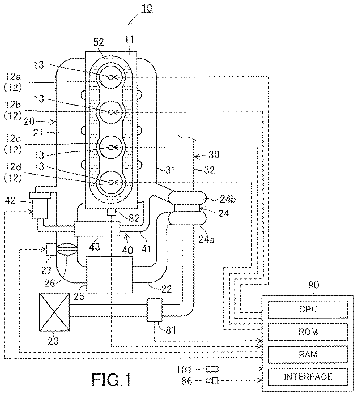
[0045]Below, a cooling apparatus of an internal combustion engine according to an embodiment of the invention will be described with reference to the drawings. The cooling apparatus according to the embodiment is applied to an internal combustion engine 10 shown in FIG. 1 and FIG. 2. Hereinafter, the cooling apparatus according to the embodiment will be referred to as “the embodiment apparatus.” The engine 10 is a multi-cylinder (in this embodiment, linear-four-cylinder) four-cycle piston-reciprocation type diesel engine. The engine 10 may be a gasoline engine.

[0046]As shown in FIG. 1, the engine 10 includes an engine body 11, an intake system 20, an exhaust system 30, and an EGR system 40.

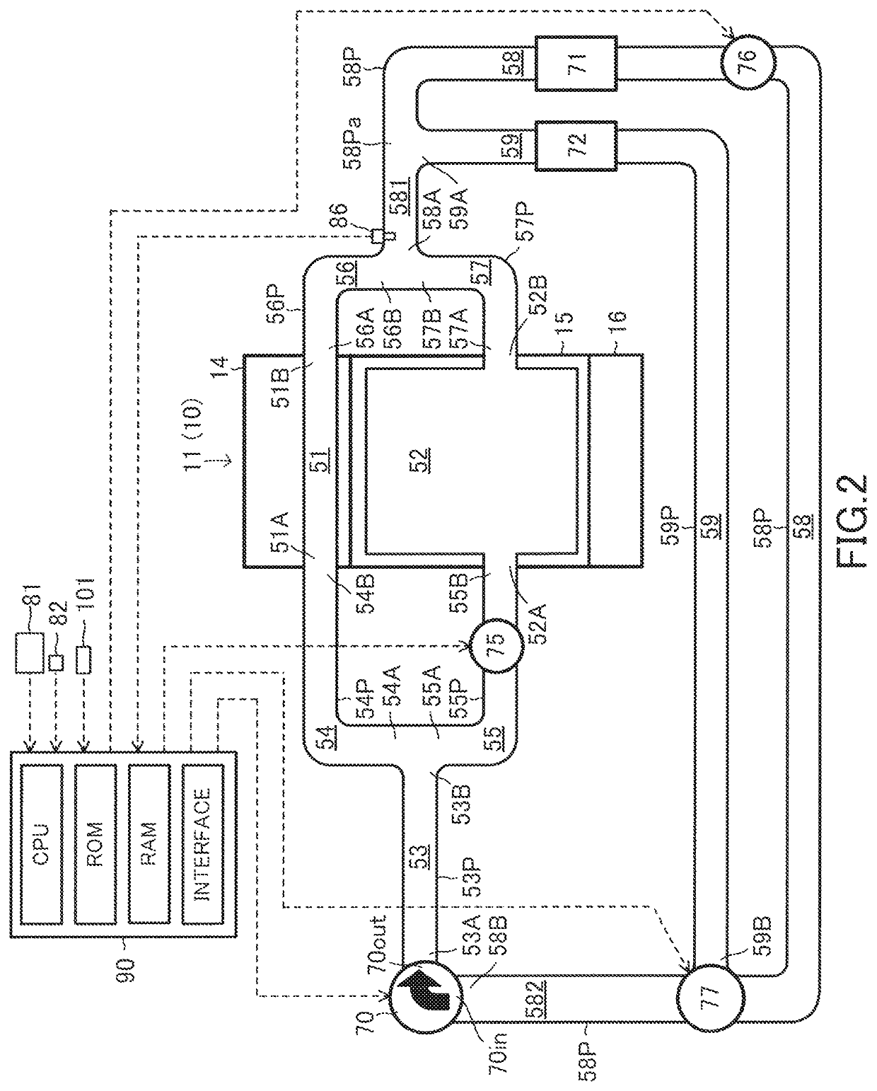
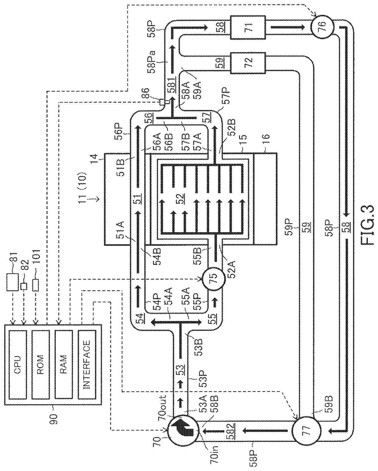
[0047]As shown in FIG. 2, the engine body 11 includes a cylinder head 14, a cylinder block 15, a crank case 16 and the like. As shown in FIG. 1, four cylinders or combustion chambers 12a to 12d are formed in the engine body 11. Fuel injectors 13 are provided such that the fuel injectors 13 expose ...


PUM


Abstract

A cooling apparatus of an internal combustion engine according to the invention controls an activation of a flow rate changing valve such that a block water flow rate proportion when an engine output is relatively large in a range of the engine output equal to or larger than a predetermine engine output, is larger than the block water flow rate proportion when the engine output is relatively small in the range of the engine output equal to or larger than a predetermine engine output.

Description

BACKGROUNDField[0001]The invention relates to a cooling apparatus of an internal combustion engine for cooling the internal combustion engine by cooling water.Description of the Related Art[0002]There is known a cooling apparatus of the internal combustion engine for controlling a flow rate of the cooling water flowing through a water passage formed in a cylinder head of the engine and a flow rate of the cooling water flowing through a water passage formed in a cylinder block of the engine, independently (see JP 2005-315106 A). Hereinafter, the flow rate of the cooling water flowing through the water passage formed in the cylinder head will be referred to as “the head water flow rate”, and the flow rate of the cooling water flowing through the water passage formed in the cylinder block will be referred to as “the block water flow rate.”[0003]The known cooling apparatus is configured to increase the head water flow rate and decrease the block water flow rate as an engine load corresp...

Claims


Application Information

Patent Timeline
Patent Type & Authority Patents(United States)
IPC IPC(8): F01P7/16F01P3/04F02F1/10F01P3/02F01P7/14
CPCF01P7/167F01P3/04F01P7/164F02F1/10F01P2003/027F01P2007/146F01P3/02F01P5/12F01P7/14
Inventor HIRATA, YOSHIHARUMIYOSHI, YUJISHINAGAWA, TOMOHIROSUGIHARA, HIROYUKI
Owner TOYOTA JIDOSHA KK
Why Eureka
Eureka Blog
Learn More