Implant devices with a pre-set pulley system

a technology of pulley system and implant device, which is applied in the field of implant device with a preset pulley system, can solve the problems of difficult to achieve configuration, difficulty in inserting nerve ends into a properly sized sleeve or cap, etc., and achieves the effects of facilitating better and faster healing, minimizing incorrect neuronal growth, and reducing the risk of fractur

Active Publication Date: 2021-03-16
AXOGEN CORP
View PDF17 Cites 2 Cited by
  • Summary
  • Abstract
  • Description
  • Claims
  • Application Information

AI Technical Summary

Benefits of technology

[0009]The subject invention addresses the disadvantages associated with the previously known nerve sheaths, such as nerve sleeve and nerve cap devices, and their methods of use, and provides attributes and advantages that have not been realized by those known devices. In particular, the subject invention provides novel, inexpensive, and highly effective improvements to currently known implant devices used to separate and isolate nerve ends and coaptation sites.
[0011]Other embodiments of a pre-set pulley system can be used to pull or draw the nerve ends into the sheath implant device, so that they come together properly, with minimal bending, crimping, or distortion of the facing end. When coapting two nerve ends within an implant device, such as a nerve sleeve, the facing ends can be properly aligned and spaced using this coapting pulling system. If drawing one nerve end into a nerve cap, the facing end can be fully directed towards the closed end of the nerve cap, to minimize incorrect neuronal growth. This coapting pulley system can position nerve ends more advantageously within the sheath implant device, which can facilitate better and faster healing. With this system, at least one, ideally at least two, sutures, or similar type of device is passed through the wall of a nerve sleeve or nerve cap, so that the tag end of the suture is outside of the implant device bore and the other, needle end, goes through the bore and out of one of the apertures. The needle end can be passed through a nerve, or at least the epineurium, and secured by knotting followed by removal of the needle. The free tag end, outside the bore, can then be pulled away from the bore, which simultaneously draws or pulls the nerve end at the other end of the suture line through the aperture and into the bore.
[0012]Variations or combinations of both of these types of pulley systems can be used with nerve repair sleeves and nerve repair caps implanted in patients in need of such treatment. While the use of the pulley systems can require one or more additional sutures at the nerve end, which has the potential to further damage neurons already in need of repair, it can reduce the number of sutures needed around the aperture to secure the implant device to the nerve. Thus, nerve healing could still be faster or at least no more inhibited by the use of the pulley system. In the case of a nerve stump, neuronal damage at the nerve end is often of minor concern, since reduction in neuronal growth is typically the purpose of utilizing a nerve repair cap.

Problems solved by technology

Likewise, nerve stumps often heal more effectively if the nerve face is directed fully into the nerve repair cap and does not fold or bunch-up, which can undesirably encourage nerve fibers to grow out of the cap instead of towards the end of the cap.
These configurations can be difficult to achieve when pushing, poking, or otherwise trying to manipulate soft nerve tissue into the aperture, or open end, of a nerve sheath implant.
Thus, the difficulty of inserting nerve ends into a properly sized sleeve or cap must be weighed against the necessity of having to use additional sutures to secure an oversized sleeve or cap.

Method used


Image

  • Implant devices with a pre-set pulley system
  • Implant devices with a pre-set pulley system
  • Implant devices with a pre-set pulley system

Examples


Embodiment Construction

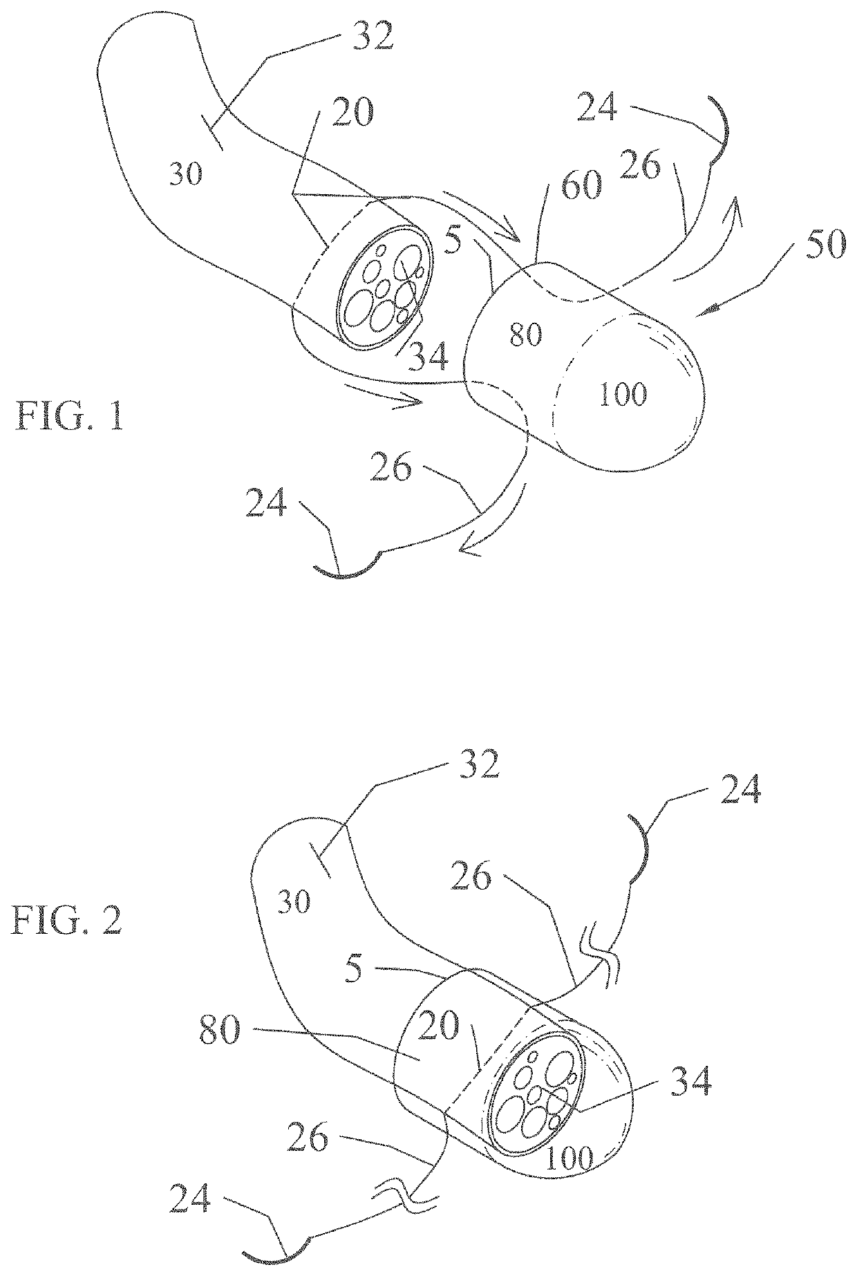
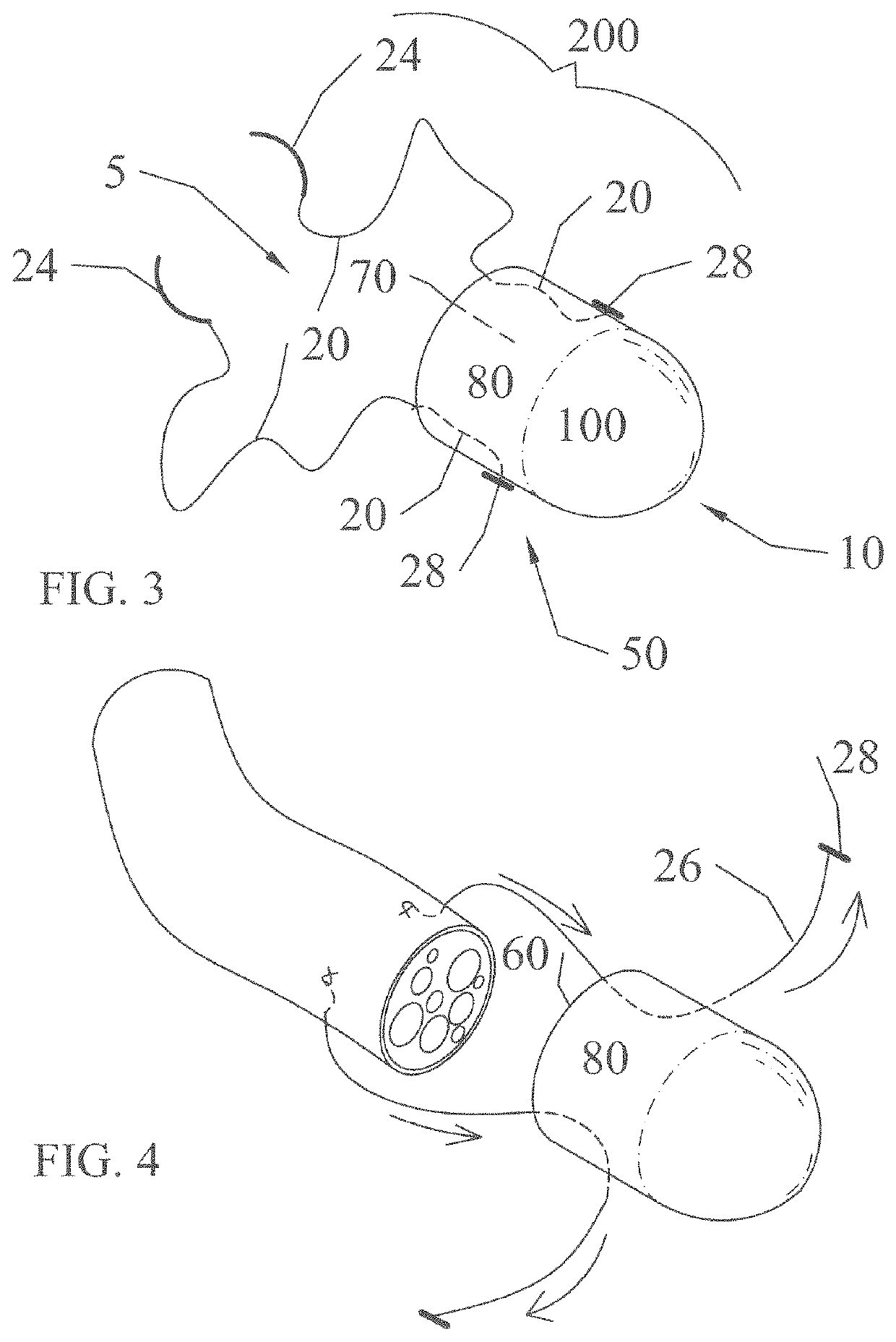
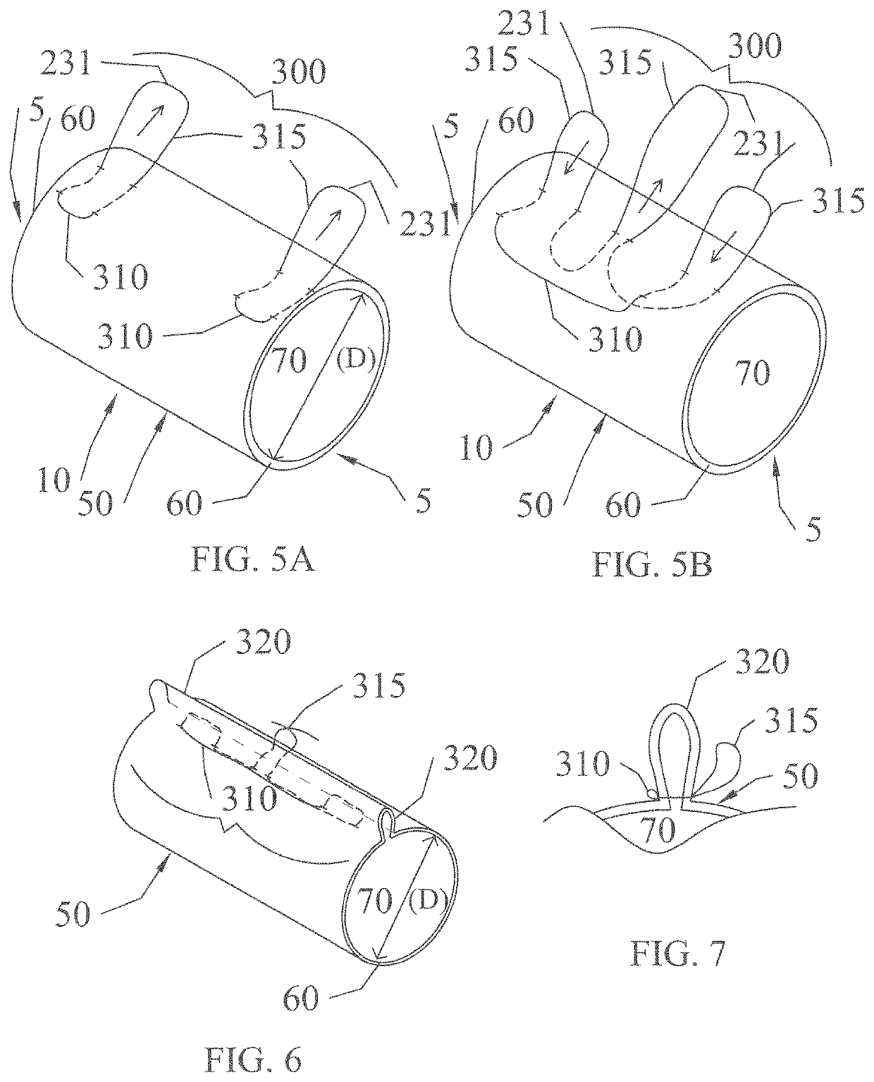
[0038]The subject invention pertains to embodiments of a sheathing implant, such as a nerve sleeve, nerve cap, or similar type of flexible implant capable of positioning and isolating nerve ends to facilitate nerve repair or prevent / isolate end bulb neuromas. More specifically, the subject invention provides sheathing implants capable of being used to coapt nerves to each other or to such sheathing implant. In particular there are provided sheathing implants with one or more suture pulley systems that can be used to attach to a nerve end and pull or draw the nerve end into the implant. Other embodiments provide nerve repair sheathing implants with a cinching loop that can be used to conform an implant to the shape and / or size of a nerve therein. These pulley systems can be used independently or in various combinations to effect a safe, secure, easy nerve repair in patients in need of such treatment.

[0039]The subject invention is particularly useful in the field of nerve repair, in p...


PUM


Abstract

The problem of positioning one or more nerve ends inside a sheathing implant is solved by the use of a pulley and cinching systems that pull a nerve end into an implant and that can adjust the diameter of an implant to conform the implant to the diameter of the nerve, respectively. The pulley system utilizes a suture that traverses the wall of an implant leaving one end outside the implant wall and another end that can be attached to a nerve. Pulling the suture end outside the wall pulls the nerve attached to the other end of the suture into the bore of the implant. A cinching system utilizes specially arranged sutures within the wall of an implant to tighten or cinch up the wall after a nerve is placed therein, so as to conform at least part of the implant to the diameter of the nerve. Methods are also disclosed by which such pulley systems can be formed during an intraoperative procedure.

Description

CROSS-REFERENCE TO A RELATED APPLICATION[0001]This application claims the benefit of U.S. provisional application Ser. No. 62 / 247,938, filed Oct. 29, 2015, which is incorporated herein by reference in its entirety.[0002]This invention was made with government support under contract no. W81XWH-13-1-0448 awarded by the Department of Defense. The government has certain rights in the invention.BACKGROUND OF INVENTION[0003]After a nerve injury, direct coaptation of the nerve ends provides the most favorable results for nerve regeneration. Successful nerve regeneration can be further promoted if the coaptation site or neurorraphy line is separated and isolated from the surrounding tissues, which can inhibit the formation of scar tissue and neuromas. Neuromas often result from nerve fibers or neurons that improperly and irregularly grow into the surrounding tissue. In situations where a nerve is not, or cannot, be repaired, there can be left a nerve stump that must be isolated or covered t...

Claims


Application Information

Patent Timeline
Patent Type & Authority Patents(United States)
IPC IPC(8): A61B17/11A61B17/04
CPCA61B17/1128A61B17/0487A61B17/0466A61B2017/0417A61B2017/0475A61B2017/0477A61B2017/0496A61B2017/1132A61B2017/1142
Inventor DEISTER, CURT
Owner AXOGEN CORP
Why Eureka
Try Eureka