Supercharge Your Innovation With Domain-Expert AI Agents!

Repeating nail-feeding structure for pneumatic nailing machine

a pneumatic nailing machine and feeding structure technology, applied in the field of pneumatic nailing machines, can solve the problems of inconvenient use and waste of time in extensive us

Active Publication Date: 2021-03-23
ANN CHAIN ENTERPRISE
View PDF25 Cites 0 Cited by
  • Summary
  • Abstract
  • Description
  • Claims
  • Application Information

AI Technical Summary

Benefits of technology

The present invention provides a repeating nail-feeding structure for a pneumatic nailing machine that allows for extensive use. The structure includes an air stream guiding tube, an automatic return cylinder, and a shifting element. The working air stream ejects the strip nail when the user pushes the pushing part, and the used air stream is directed into the automatic return cylinder through the air stream guiding tube. The piston stein is then moved back to its original position through the return spring, allowing the shifting lever to push the strip nail back and forth. This invention allows for quicker and more efficient use of the pneumatic nailing machine.

Problems solved by technology

Once this strip staple unit is used up, a new strip staple unit should be reloaded, which is considerably inconvenient and a waste of time in extensive use.

Method used


Image

  • Repeating nail-feeding structure for pneumatic nailing machine
  • Repeating nail-feeding structure for pneumatic nailing machine
  • Repeating nail-feeding structure for pneumatic nailing machine

Examples


Embodiment Construction

[0012]The detailed description and technical content of the present invention will be described, in conjunction with drawings, as follows.

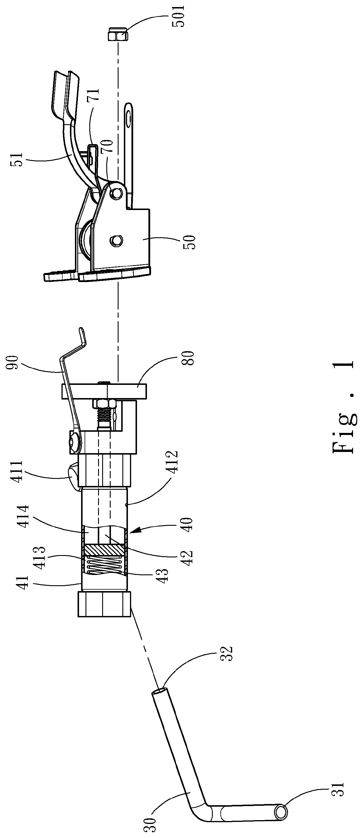
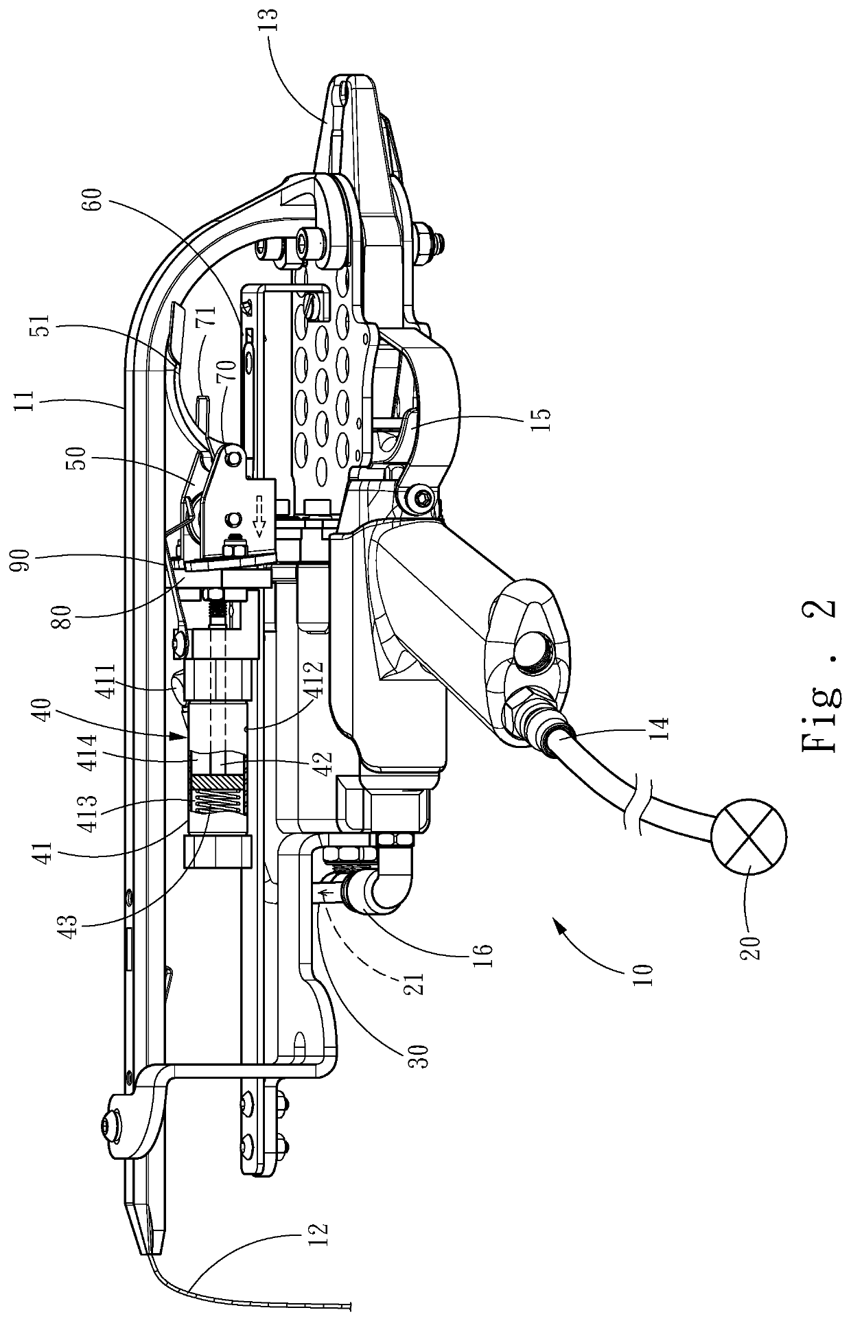
[0013]Referring to FIG. 1 and FIG. 2, there are shown a structural exploded view and a diagram illustrating a first state of one preferred embodiment of the present invention. As illustrated in the figures, the present invention is a repeating nail-feeding structure for a pneumatic nailing machine 10, installed in the pneumatic nailing machine 10, the pneumatic nailing machine 10 including a magazine 11 loaded with a strip nail 12, a nail-discharging head 13 connected to the magazine 11 and receiving the strip nail 12 to be ejected, an air inlet 14 connected to an air pressure source 20, a pushing part 15 turning on the air pressure source 20 for supplying a working air stream 21, and an air outlet 16 discharging the working air stream 21.

[0014]The nail-feeding structure comprises an air stream guiding tube 30, an automatic return cylinder 40, and...


PUM


Abstract

A repeating nail-feeding structure for pneumatic nailing machine, installed in a pneumatic nailing machine, includes an air stream guiding tube, automatic return cylinder, and shifting element. The tube enables working air stream from the machine to enter the cylinder, thereby a piston stein of the cylinder is driven to a retracted position. The piston stein is returned to an extended position by the pressing of a return spring within the cylinder. The shifting element is fixed to the piston stein and provided with a shifting lever. The shifting lever is moved along with the piston stein to advance the strip nail of the machine. Thereby, when the nail is ejected, the strip nail is advanced simultaneously by the discharged working air stream. The requirement of extensive use is fulfilled due to no limitation to length of the strip nail and successive nail-feeding capability.

Description

FIELD OF THE INVENTION[0001]The present invention is related to a pneumatic nailing machine, particularly to a nail-feeding structure for a pneumatic nailing machine.BACKGROUND OF THE INVENTION[0002]A pneumatic tool, such as a pneumatic stapler, is a tool outputting kinetic energy to work by driving a pneumatic motor using compressed air supplied by an air compressor. There are advantages, including faster motion, wide adaptability, operability in rough conditions, such as inflammability, explosibility, dampness, impact and etc., no contamination, long service life, simple construction, easy maintenance and so on.[0003]The stapler is a tool used in building and decorating, in which different workpieces are joined together with staples fired by the stapler. The conventional stapler, such as Taiwan patent no. 1603818, entitled “MAGAZINE ASSEMBLY AND A STAPLER INCLUDING THE SAME”, disclosed a magazine assembly and a stapler including the same. The magazine assembly includes a base and ...

Claims


Application Information

Patent Timeline
Patent Type & Authority Patents(United States)
IPC IPC(8): B25C1/00B25C1/04
CPCB25C1/003B25C1/047
Inventor CHENG, HUI-CHENG
Owner ANN CHAIN ENTERPRISE
Features
  • R&D
  • Intellectual Property
  • Life Sciences
  • Materials
  • Tech Scout
  • Unparalleled Data Quality
  • Higher Quality Content
  • 60% Fewer Hallucinations
Learn More