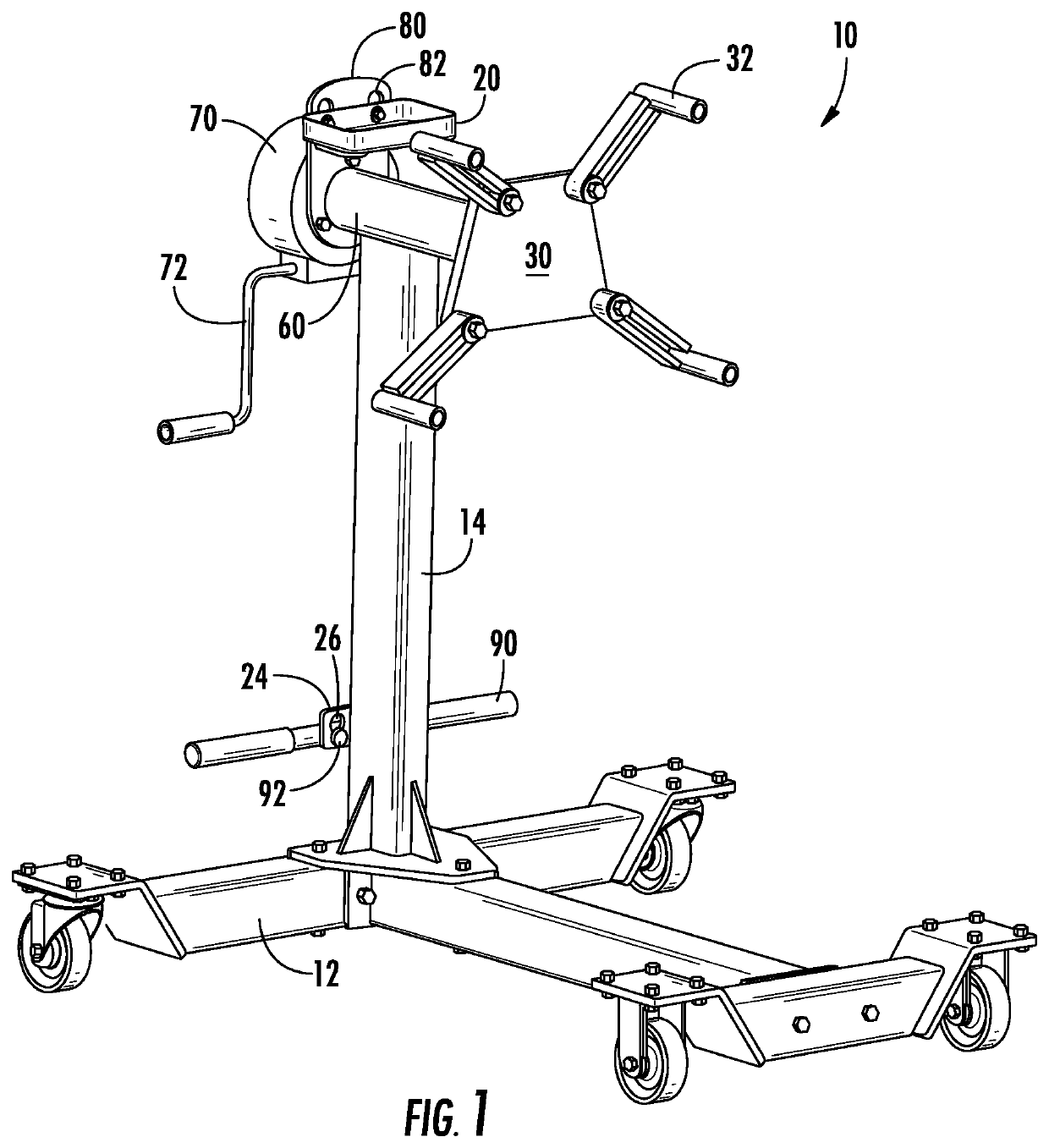
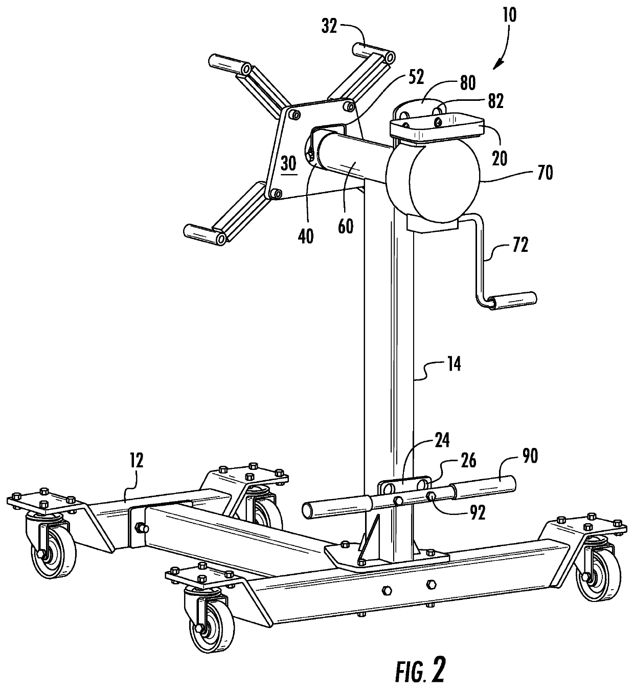
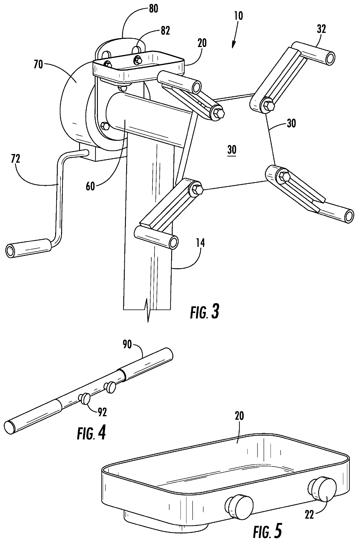
Engine stand

a technology for engine stands and crank handles, which is applied in the direction of stand/trestles, machine supports, work benches, etc., can solve the problems of not being able to use the crank handle for steering and maneuvering the engine stand, and the mounting head cannot be removed and mounted to the engine, so as to achieve easy and quick removal and installation

Active Publication Date: 2021-04-27
VIS
View PDF9 Cites 1 Cited by
  • Summary
  • Abstract
  • Description
  • Claims
  • Application Information

AI Technical Summary

Benefits of technology

[0006]It is at least one aspect of one embodiment of the present invention to provide for a steering handle for a worm gear engine stand that can be easily and quickly removed and installed and will not interfere with the operation of the crank handle, the crank handle being used to engage and disengage the worm drive of the engine stand.
[0007]It is a further aspect of at least one embodiment of the present invention to provide for a steering handle that is easily and quickly removed from a work position that is elevated above the worm drive gear and the drive shaft.
[0025]placing the steering handle on the adaptor plate, thereby allowing the user to engage the handle for moving the engine stand.

Problems solved by technology

While a worm gear construction provides easier and better control of the mounting head rotation, there is no ability to remove the mounting head to mount it to the engine.
Additionally, the crank handle used for rotating the mounting head can not be used for steering and maneuvering the engine stand.

Method used


Image

  • Engine stand
  • Engine stand
  • Engine stand

Examples


Embodiment Construction

[0037]Reference will now be made in detail to the embodiments of the invention, one or more examples of which are set forth below. Each example is provided by way of explanation of the invention, not limitation of the invention. In fact, it will be apparent to those skilled in the art that various modifications and variations can be made in the present invention without departing from the scope or spirit of the invention. For instance, features illustrated or described as part of one embodiment can be used on another embodiment to yield a still further embodiment. Thus, it is intended that the present invention cover such modifications and variations as come within the scope of the appended claims and their equivalents. Other objects, features, and aspects of the present invention are disclosed in the following detailed description. It is to be understood by one of ordinary skill in the art that the present discussion is a description of exemplary embodiments only and is not intende...


PUM


Abstract

A wheeled engine stand and a process of using the engine stand is provided. The engine stand provides a wheeled base supporting a mounting head with retainers. The mounting head is reversibly attached to a drive shaft through, a retaining pin extending through a mounting head collar. A steering handle is detachably supported on an upper adaptor plate to allow for movement for the wheeled base.

Description

FIELD OF THE INVENTION[0001]This invention is directed towards a geared engine stand that offers improvements in mobility, utility, and provides for an engine mounting head that is detachable from a drive shaft. The detachable mounting head allows for easier installation of the mounting head onto an engine. Following mounting of the mounting head, the engine stand is then reconnected.BACKGROUND OF THE INVENTION[0002]It is known in the art to provide engine stands that can be used to attach to an engine and move the engine within the confines of a repair shop. A common characteristic of an engine stand is that they employ some form of a rotating method to allow the rotation of an attached engine. Frequently, the rotation occurs in six equal increments and is controlled by a mounting plate tube that is activated by a handle connected to an opposite end of the tube. When the mounting plate tube is locked into position, the handle can be used to steer and maneuver the engine stand.[0003...

Claims


Application Information

Patent Timeline
Patent Type & Authority Patents(United States)
IPC IPC(8): F16M11/00B25H1/00F16M11/04F16M11/42B66C23/48
CPCB25H1/0007F16M11/04F16M11/42B66C23/485F16M11/041F16M11/16
Inventor FOX, ROBERT
Owner VIS
Why Eureka
Try Eureka