Pitch adjustment for a valve brass musical instrument

a brass musical instrument and pitch adjustment technology, applied in the field of brass instruments, can solve the problems of inconvenient change between slide positions, instruments producing high notes, instruments producing low notes, etc., and achieve the effect of reducing pitch, accurate initial adjustment of tubing, and reducing the pitch

Active Publication Date: 2021-05-11
BAHR JUSTIN ANDREW
View PDF14 Cites 0 Cited by
  • Summary
  • Abstract
  • Description
  • Claims
  • Application Information

AI Technical Summary

Benefits of technology

[0008]There are ways to compensate for this. One way is to provide a fourth valve that itself directs the air flow to bypass or pass through an additional tube that lowers the pitch by five semitones. The fourth valve allows for accurate initial adjustment of the tubing to reduce the pitch by one, two, three, and five semitones, without the need for a player to adjust the tubing while playing the instrument. One can also provide additional valves, for example, a fifth and sixth valve. The valve and tube for a fourth (or additional) valve, however, adds weight and bulk to the instrument and an instrument with four or more valves would be playable only by an advanced musician.
[0009]Another way is to provide for adjustment of the first additional tube and third additional tube. Brass instruments with valves often include a tuning slide adjustment on the additional tubes to permit the length of the additional tube for each valve to be individually adjusted. This tuning slide adjustment permits a player to adjust the length of the first and / or third additional tube to reach the correct pitch when valves are used in combination.

Problems solved by technology

Tight lips and a fast stream of air pushed through them cause a high frequency of vibrations, resulting in the instrument producing a high note.
Conversely, looser lips cause a low frequency of vibrations, resulting in the instrument producing a low note.
The slide allows for continuous change in tubing length, but changing between slide positions can take more time than desirable, especially when changing between distant slide positions.

Method used


Image

  • Pitch adjustment for a valve brass musical instrument
  • Pitch adjustment for a valve brass musical instrument
  • Pitch adjustment for a valve brass musical instrument

Examples


Embodiment Construction

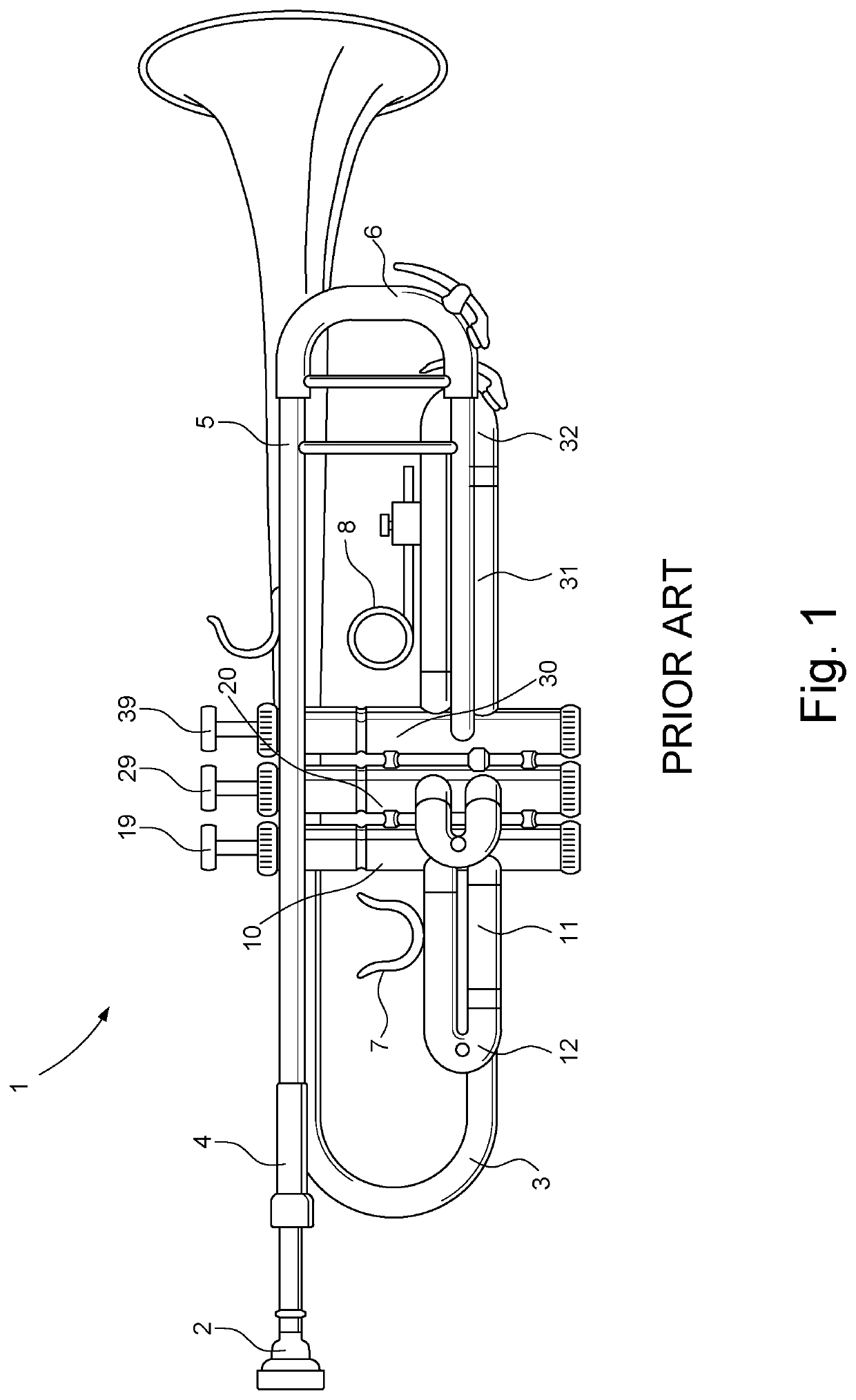
[0029]FIG. 1 shows a side view of a conventional B♭ trumpet 1 having a mouthpiece 2 and a main tube 3 leading to a bell 9. The main tube 3 has a mouthpiece receiver 4, a lead pipe 5, and a main tuning slide 6 for tuning the trumpet. The trumpet also includes three piston valves, a first valve 10 for selectively diverting air flow to a first additional tube 11, a second valve 20 for selectively diverting air flow to a second additional tube 21, and a third valve 30 for selectively diverting air flow to a third additional tube 31. The valves 10, 20, 30 and additional tubes 11, 21, 31 allow for the length of the tubing through which the air flow passes between the mouthpiece 2 and bell 9 to be changed, which changes the pitch of the trumpet 1 within a harmonic partial.

[0030]The trumpet also includes three valve keys for engagement by the player's finger to selectively operate each valve, a first valve key 19 that when depressed moves the first valve 10 into a position in which it diver...


PUM


Abstract

Disclosed is a pitch adjuster for a musical instrument having valves for selectively directing air flow through additional tubes and tuning slides on at least some of the additional tubes. The pitch adjuster automatically adjusts the tuning slides depending upon which valves are directing the air flow to pass through their additional tubes. There are a pair of adjustable linear solenoids connected between the additional tubes and their tuning slides, each of which adjusts the tuning slide when the solenoid is energized. There are sensors to detect whether each valve is directing the air flow through its additional tube. There is also a controller connected to sensors and solenoid for energizing the selected solenoids when the controller receives input from at least two sensors that the valves are directing the air flow to pass through their additional tubes.

Description

FIELD OF THE INVENTION[0001]The invention pertains to brass instruments in which pitch is adjusted by the use of a set of valves.BACKGROUND OF THE INVENTION[0002]Brass musical instruments, and trumpets in particular, use valves to change their pitch and commonly have tuning slides on their additional tubes to allow for tuning of the additional tube of each valve. Newman (U.S. Pat. No. 1,662,076), Holland (U.S. Pat. No. 4,276,804), and Holland (U.S. Pat. No. 4,512,233) each disclose a trumpet in which there is a finger trigger mechanism for adjusting the third valve additional tube tuning slide. Sawada et al. (U.S. Pat. No. 7,786,372) disclose a trumpet in which a solenoid actuator is used to operate the valves in response to sensors detecting finger pressure on the valve keys. Catalano et al. (U.S. Pat. No. 10,249,270) disclose a system for compromise tuning a valve operated instrument in which the tuning slide is moved by the musician or an actuator. Thibodeau et al. (Trumpet Augme...

Claims


Application Information

Patent Timeline
Patent Type & Authority Patents(United States)
IPC IPC(8): G10D9/01F16K31/06G10D9/04G10D7/10F16K37/00
CPCG10D9/01F16K31/0675F16K37/00G10D7/10G10D9/04
Inventor BAHR, JUSTIN ANDREW
Owner BAHR JUSTIN ANDREW
Why Eureka
Try Eureka