Monotube piston valving system with selective bleed

a valve system and monotube technology, applied in the direction of shock absorbers, vibration dampers, springs/dampers, etc., can solve the problems of increasing the cost and complexity of shock absorbers, reducing damping effectiveness, and difficult to obtain damping force at relatively low piston velocities

Inactive Publication Date: 2006-07-04
TENNECO AUTOMOTIVE OPERATING CO INC
View PDF7 Cites 30 Cited by
  • Summary
  • Abstract
  • Description
  • Claims
  • Application Information

AI Technical Summary

Benefits of technology

[0038]Piston assemblies of the present invention offer several advantages. By using simplified plate designs, and spring loading or preloading each plate using a simple spring or plurality of spring plates, the design of the present invention is mechanically simplified. In one embodiment, the preload spacers (welded following preloading of the blow-off disc plate(s)), allow a very accurate initial adjustment of the damping force characteristic because a load of the blow-off disc(s) is first measurable and then fixable by the weld. Valve stems normally associated with valves isolating the bleed passages or the blow-off passages are eliminated by the piston assembly design of the present invention. There is also no requirement for fasteners at either end of the bleed or blow-off passages associated with the valves. Also, by varying the diameter, thickness and / or quantity of interface discs in a piston assembly of the present invention, a common piston can be used in several shock absorber designs, providing different design lift pressures for each. This reduces manufacturing and storage costs of component parts. The disc designs of the present invention also permit the piston assembly to operate with reduced chatter over a full range of operating flow rates.
[0039]While the above detailed description describes the preferred embodiments of the present invention, it should be understood that the present invention is susceptible to modification, variation and alteration without deviating from the scope and fair meaning of the subjoined claims.

Problems solved by technology

Because of the exponential relation between the pressure drop and flow rate, it is difficult to obtain a damping force at relatively low piston velocities, particularly at velocities near zero.
Activation of the high speed stage valving at relatively low velocities creates harshness because the shape of the fixed orifice bleed circuit force velocity characteristic is totally different than the shape of the high speed circuit.
Use of valves increases the cost and complexity of the shock absorber.
Valves can also “chatter” during operation decreasing damping effectiveness and potentially increasing the potential for rapid wear of the valve parts.

Method used


Image

  • Monotube piston valving system with selective bleed
  • Monotube piston valving system with selective bleed
  • Monotube piston valving system with selective bleed

Examples


Embodiment Construction

[0021]The following description of the preferred embodiments is merely exemplary in nature and is in no way intended to limit the invention, its application, or uses.

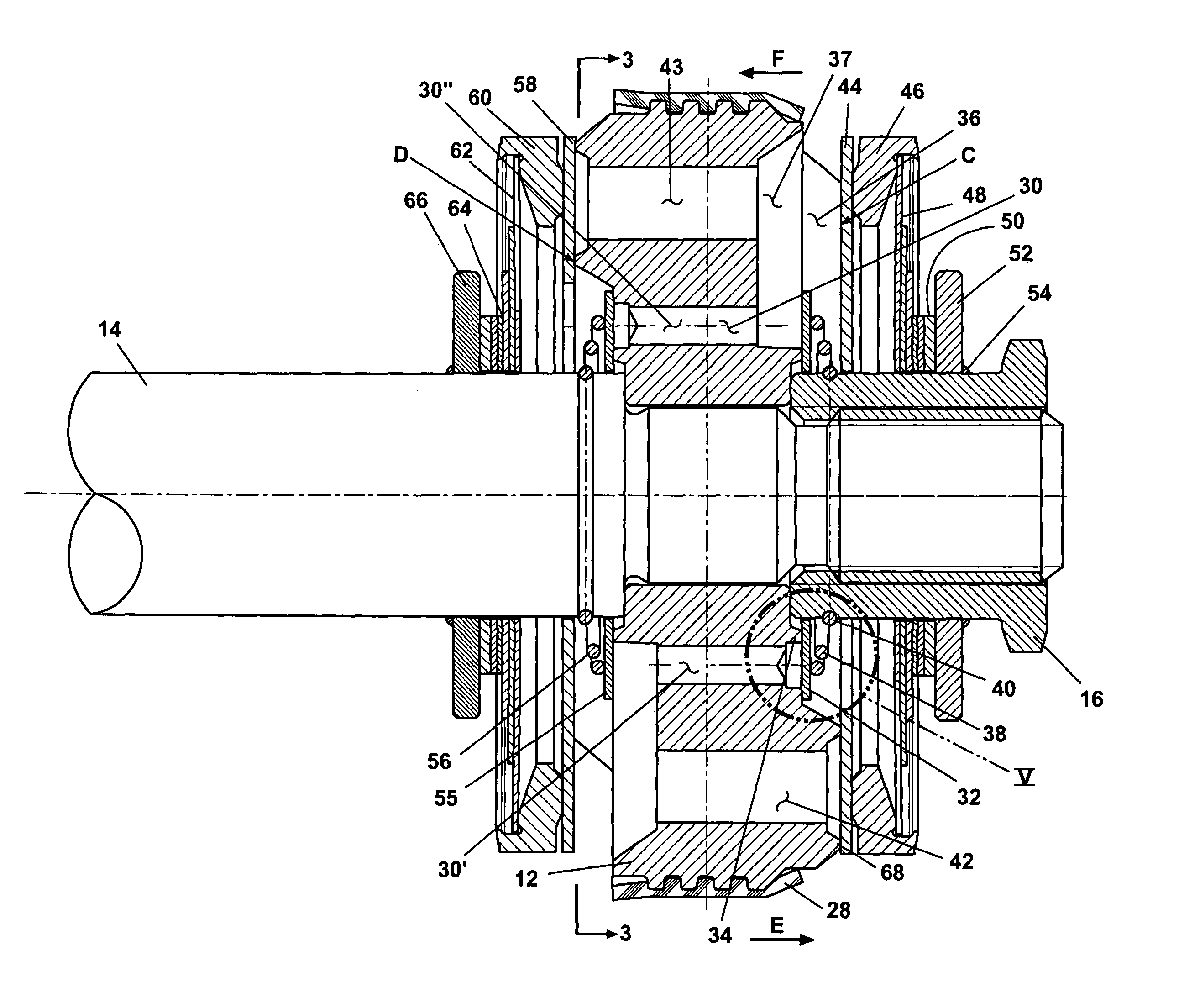
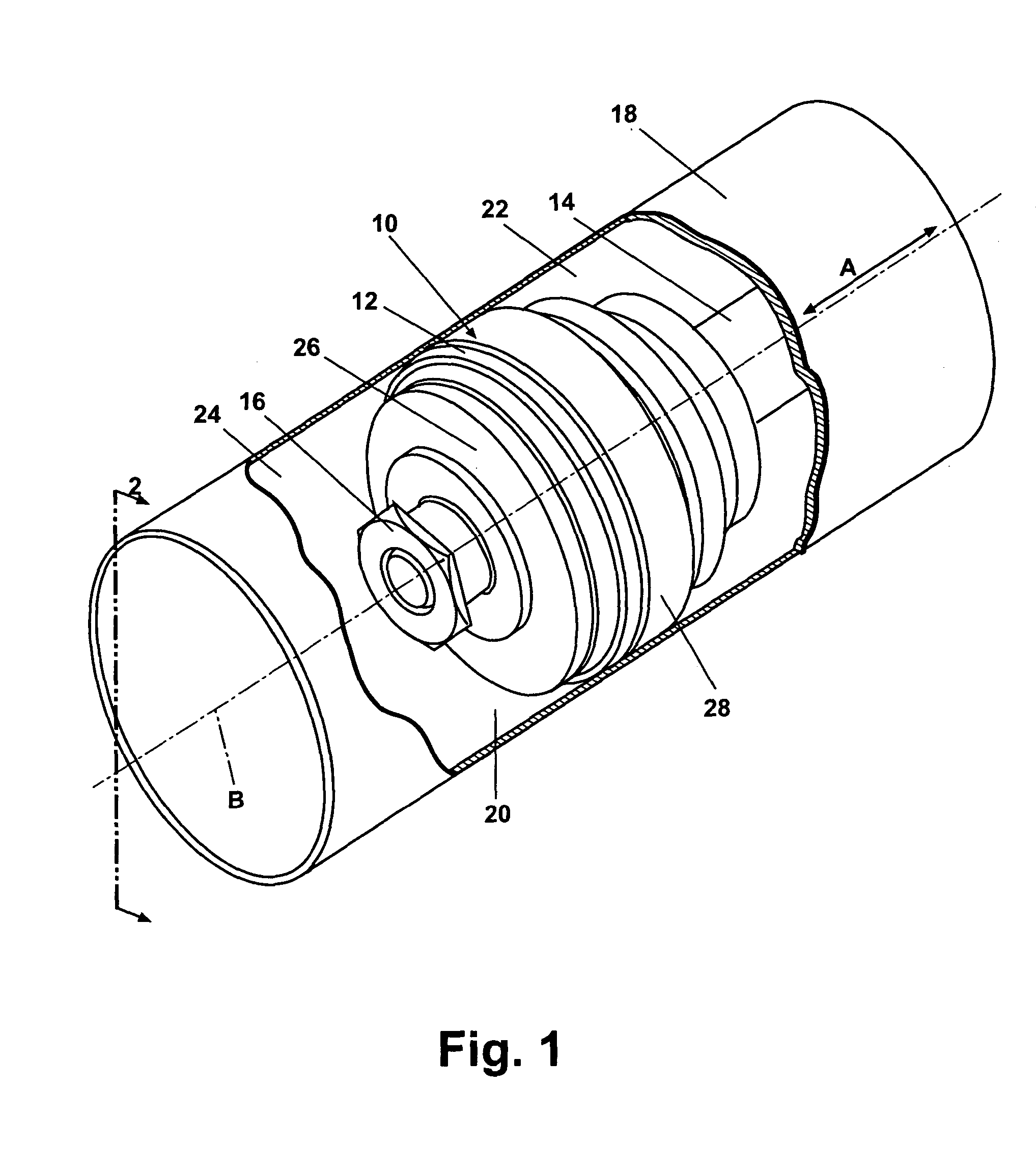
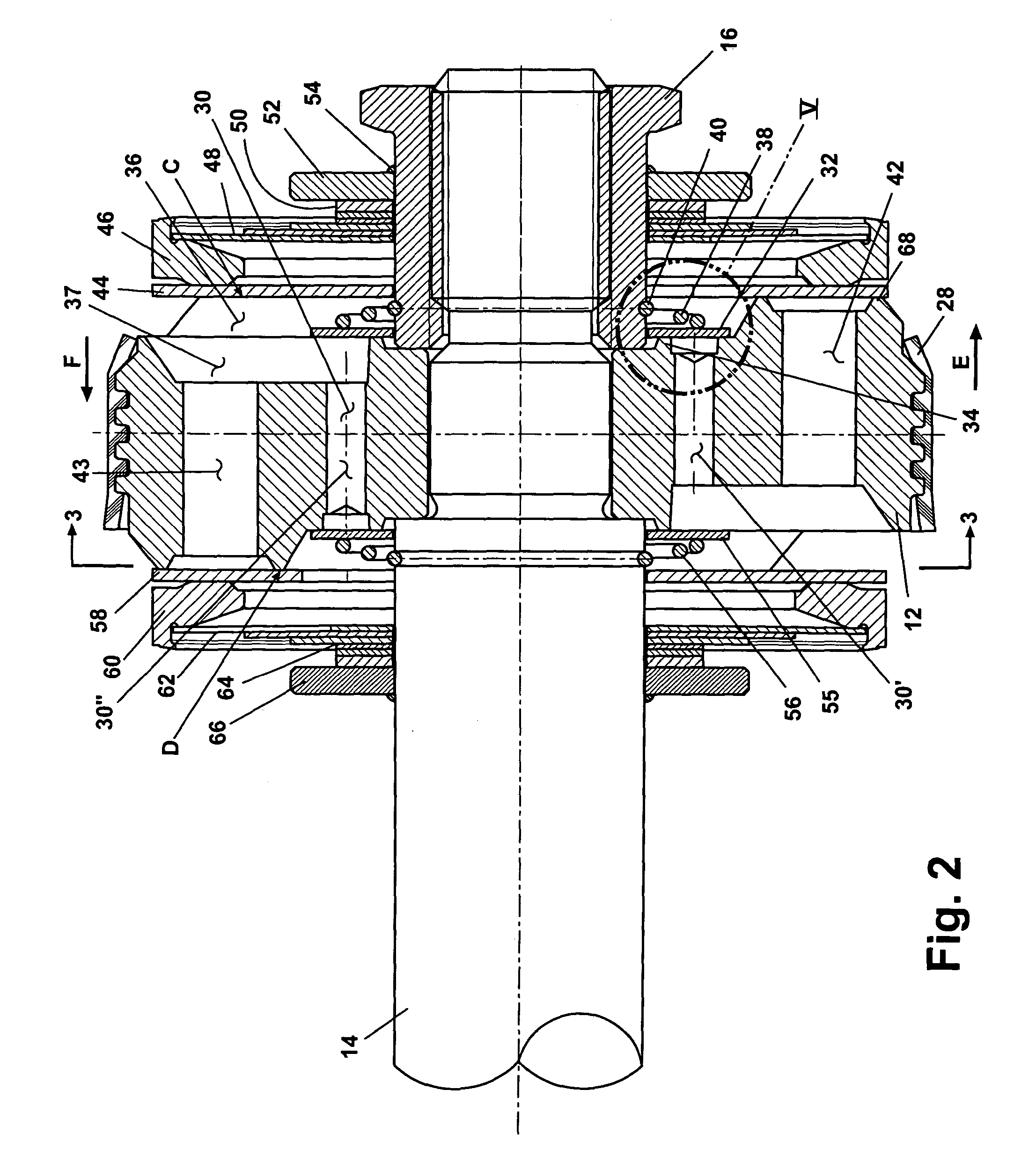
[0022]According to a preferred embodiment of the present invention, and as shown in FIG. 1, a piston assembly 10 includes a piston 12 fastenably connected to a piston rod 14 by a nut 16. Piston assembly 10 is slideably disposed within a tube 18 and is free to slide within tube 18 in the direction of piston travel arrows “A”. Piston 12 divides tube 18 into a first working chamber 20 and a second working chamber 22 respectively. A fluid 24 in either first working chamber 20 or second working chamber 22 flows between either of the working chambers when piston 12 slides within tube 18. Fluid flow is controlled by a plurality of flow control devices 26 which will be described in further detail in reference to FIG. 2. Piston assembly 10 and tube 18 share a common longitudinal centerline “B”. Fluid 24 within tube 18 is prevent...


PUM


Abstract

A shock absorber piston assembly includes a piston having a first face, a second face and a plurality of fluid passages. Preloaded flow control devices each seal at least one of the fluid passages, including: a first bleed plate contacting the first face and a second bleed plate contacting the second face; and a pair of blow-off discs, with a first blow-off disc contacting the first face and a second blow-off disc contacting the second face. Each of the flow control devices opens at an individually adjustable device opening pressure. Each of the multiple passages in contact with the blow-off discs can also differ in flow area to permit the blow-off discs to angularly lift to limit disc chatter.

Description

FIELD OF THE INVENTION[0001]The present invention generally relates to automotive shock absorbers. More specifically, the present invention relates to a hydraulic flow control assembly operable as valves which allow greater tunability of the shock absorber.BACKGROUND OF THE INVENTION[0002]Shock absorbers are used in conjunction with automotive suspension systems to absorb unwanted vibrations which occur during driving. Shock absorbers are generally connected between the sprung portion (body) and the unsprung portion (wheels) of the automobile. A piston is located within a working chamber defined by a pressure tube of the shock absorber, with the piston being connected to the sprung portion of the automobile through a piston rod. The pressure tube is connected to the unsprung portion of the vehicle by one of the methods known in the art. Because the piston is able, through valving, to limit the flow of damping fluid between opposite sides of the piston when the shock absorber is comp...

Claims


Application Information

Patent Timeline
Patent Type & Authority Patents(United States)
IPC IPC(8): F16F9/34F16F9/348F16F9/50
CPCF16F9/3485
Inventor DEFERME, STEFAN
Owner TENNECO AUTOMOTIVE OPERATING CO INC
Why Eureka
Try Eureka