Compensation device for compensating PVT variations of an analog and/or digital circuit

a compensation device and analog and/or digital circuit technology, applied in logic circuits, pulse techniques, reliability increasing modifications, etc., can solve the problems of large variability of reference voltage vrefb>1/b> over pvt variations, less attractive and easy to implement, and less energy between vsub>dd/sub>and vregb>1/b> headroom is merely dispersed

Active Publication Date: 2021-05-18
CSEM CENT SUISSE DELECTRONIQUE & DE MICROTECHNIQUE SA RECH & DEV
View PDF22 Cites 1 Cited by
  • Summary
  • Abstract
  • Description
  • Claims
  • Application Information

AI Technical Summary

Benefits of technology

[0035]Therefore, the compensation device according to the invention allows to control the current flowing in the transistor of the circuit to be compensated, by adjusting its threshold voltage through its fourth terminal. Advantageously, this allows to minimize the supply voltage of the circuit to be compensated, as the voltage headroom present in the known circuits imposed by PVT variations is not anymore necessary.
[0038]Advantageously, the compensation device according to the invention allows to reduce or even eliminate the influence of deterministic PVT variations (˜100 k fold reduction with regard to known solutions) without necessitating PVT variations monitoring structures. In fact, the compensation device according to the invention automatically and adaptively adjust the voltage at the fourth terminal depending on PVT variations.
[0039]Advantageously, the compensation device according to the invention allows to optimize dynamic power dissipation.
[0058]to the third terminal: in this case, it is possible to control the leakage currents of the digital circuit to be compensated; this is advantageous if the digital circuit comprises memory cells, e.g. SRAM cells.
[0065]According to another embodiment, the transistor is operated to work in a sub-threshold region or in a near-threshold region. One of the challenge of sub-threshold region stems from the exponential law of the transistor (the drain current is exponentially related to VGS), which leads to a rapid reduction of the circuit speed as VDD is lowered, increases the relative weight of leakage currents and yields the highest sensitivity to PVT variations. Advantageously, the compensation device according to the invention allows to eliminate all deterministic variations introduced by PVT variations, allowing the use of transistors operated in a sub-threshold region or in a near-threshold region.
[0078]The above-mentioned embodiment allows to control the current—and hence speed or delay of a digital circuit to be compensated—of both type of MOS independently, by adjusting their threshold voltages through their fourth terminals.

Problems solved by technology

The main drawback of the compensation device illustrated in FIG. 1 is the large variability of the reference voltage VREF1 over PVT variations that can exceed 800 mV, as both contributions of NMOS and PMOS threshold voltage variations add up.
Moreover, a DCDC based powering scheme more efficient than a Low-DropOut regulator (“LDO”), where the energy between the VDD and VREG1 headroom is merely dissipated, is not so attractive and easy to implement.
Moreover, unless the biasing current I is made extremely small, VREF1 will be rather large, leading to a super-VTh regime for the logic gates far from optimum regarding power dissipation, if speed requirements are moderate or low.
Under low voltage operation, in the case the transistors are operated in the sub- or near-threshold region, this can result in huge N to P type MOS current ratios, leading to large leakage currents or even compromising retention in SRAM cells of the circuit to be compensated.

Method used


Image

  • Compensation device for compensating PVT variations of an analog and/or digital circuit
  • Compensation device for compensating PVT variations of an analog and/or digital circuit
  • Compensation device for compensating PVT variations of an analog and/or digital circuit

Examples


Embodiment Construction

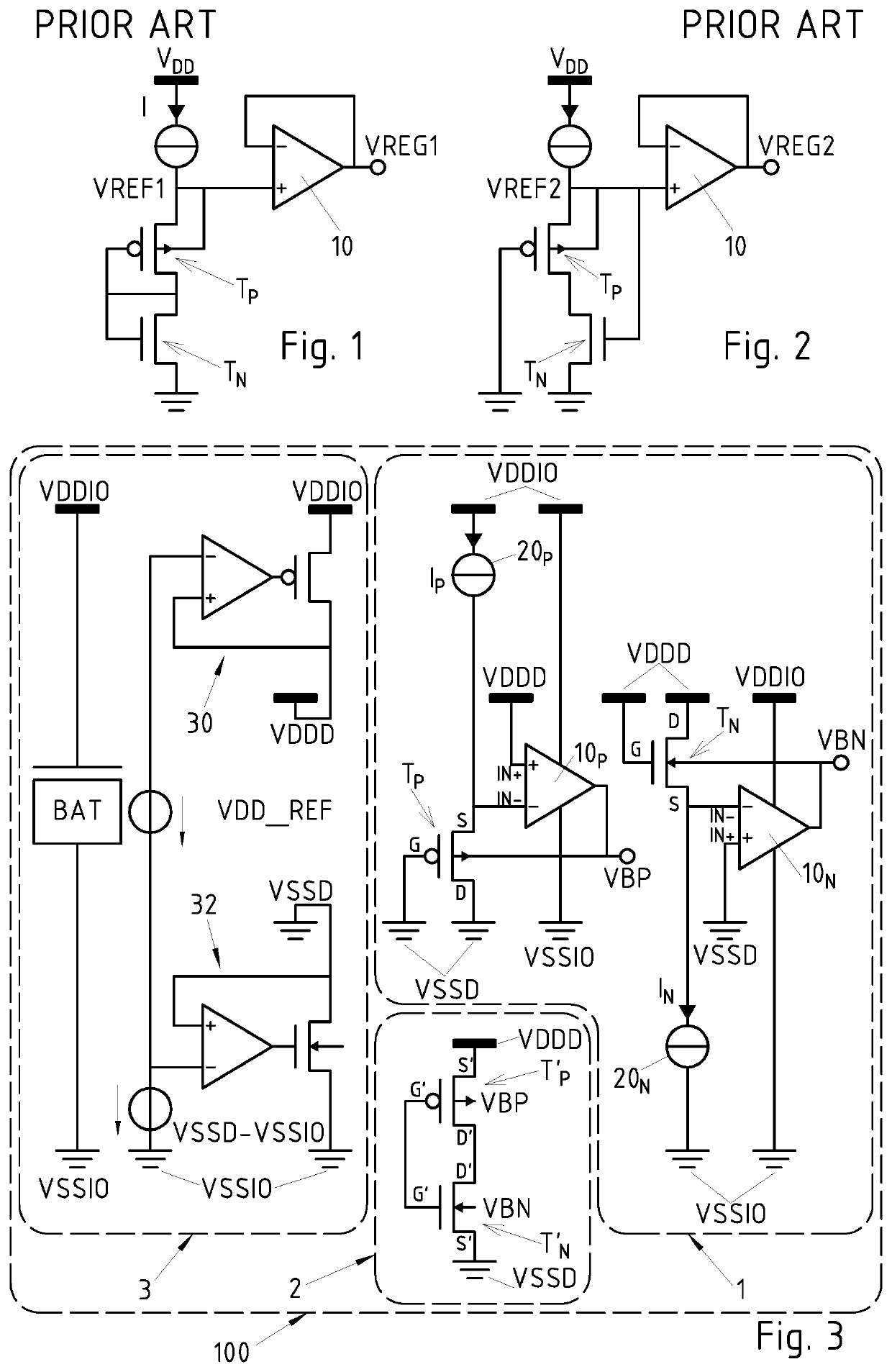
lass="d_n">[0096]FIG. 3 shows a schematic view of the electronic device 100 according to an embodiment of the invention. In the illustrated embodiment it comprises:[0097]a compensation device 1, for compensating PVT variations of an analog and / or digital circuit 2,[0098]the analog and / or digital circuit 2,[0099]an input / output circuit 3.

[0100]Examples of analog and / or digital circuits 2 to be compensated comprise, but are not limited to, voltage or current references, amplifier, oscillator, memory cells (e.g. SRAM or ROM cells), digital accelerators, processors, etc.

[0101]In the illustrated embodiment the input / output circuit 3 comprising a battery BAT, arranged for generating a voltage equal to VDDIO−VSSIO, and means 30, 32 (two LDOs in this case) arranged for generating the voltages of supply source VDDD and of the supply source VSSD of the compensation device 1 and of the analog and / or digital circuit 2. However it must be understood that other means, as DCDC converters, can be u...


PUM


Abstract

A compensation device for compensating PVT variations of an analog and / or digital circuit. The compensation device includes a transistor having a first terminal, a second terminal, a third terminal, and a fourth terminal allowing to modify a threshold voltage of the transistor. The transistor is configured to be in saturation region. The voltage at the third terminal has a predetermined value and the difference between the voltage at the second terminal and the voltage at the third terminal has a predetermined value. A current generation module is configured to generate a current of a predetermined value. A compensation module is configured to force this current to flow between the first terminal and the third terminal by adjusting the voltage of the fourth terminal.

Description

FIELD OF THE INVENTION[0001]The present invention concerns a compensation device for compensating PVT variations of an analog and / or digital circuit. In particular, the present invention concerns a compensation device allowing to adaptively and dynamically control the current of at least one transistor of an digital and / or analog circuit to be compensated, working at a given supply voltage, preferably in the sub- or near-threshold region.DESCRIPTION OF RELATED ART[0002]With the constant scaling of MOS transistors resulting in ever increasing speed performance, it has long been proposed to supply analog and / or digital circuits (e.g. and in a non-limiting way, digital gates) at lower voltages, so to spare dynamic power (equal to f·C·V2, where f is the clock frequency, C the gate capacitance being switched and V the supply voltage of the circuit), as long as required speed performance can be met.[0003]Provided the transistors are operated in strong inversion or in the super-VTh, region...

Claims


Application Information

Patent Timeline
Patent Type & Authority Patents(United States)
IPC IPC(8): H03K17/14H03K3/011H03K19/003
CPCH03K17/145H03K3/011H03K19/00384
Inventor RUFFIEUX, DAVIDSALAZAR GUTIERREZ, CAMILO ANDRESPONS SOLE, MARCSEVERAC, DANIELNAGEL, JEAN-LUCPORRET, ALAIN-SERGE
Owner CSEM CENT SUISSE DELECTRONIQUE & DE MICROTECHNIQUE SA RECH & DEV
Why Eureka
Try Eureka