3-D lidar sensor

a lidar sensor and lidar technology, applied in the field of 3d lidar sensors, can solve the problems of laser itself showing thermal drift during continuous operation, the entire sensor may be mechanically out of alignment, etc., and achieve the effect of improving functionality and reliability

Active Publication Date: 2021-06-01
ROBERT BOSCH GMBH
View PDF20 Cites 0 Cited by
  • Summary
  • Abstract
  • Description
  • Claims
  • Application Information

AI Technical Summary

Benefits of technology

[0003]An object of the present invention is to provide a 3-D lidar sensor having improved functionality and reliability, which is suitable, in particular, for motor vehicles. A corresponding method for operating the 3-D lidar sensor shall also be provided.
[0008]Furthermore, irradiation by outside light or the light of other lidar sensors of motor vehicles may be detected and suppressed, for example, in light of other frequencies, pulse durations or the like. For example, band-pass filters and / or suitable coatings, e.g., at the exit aperture, which are only transparent to light of a particular wavelength, are used to this end. However, in this case, transmission of data between the sensors of different motor vehicles would also be possible, in principle, in order, for example, to improve the flow of traffic.

Problems solved by technology

However, if this occurs, it may automatically be determined that the laser and / or the scanning system are out of alignment, and a corresponding error message may be outputted, and / or self-calibration of the entire system is carried out.
In addition, the entire sensor may be mechanically out of alignment, e.g., due to a collision of the motor vehicle.
Also, the laser itself may exhibit thermal drift during continuous operation, e.g., a laser delay after a trigger pulse.

Method used


Image

  • 3-D lidar sensor
  • 3-D lidar sensor
  • 3-D lidar sensor

Examples


Embodiment Construction

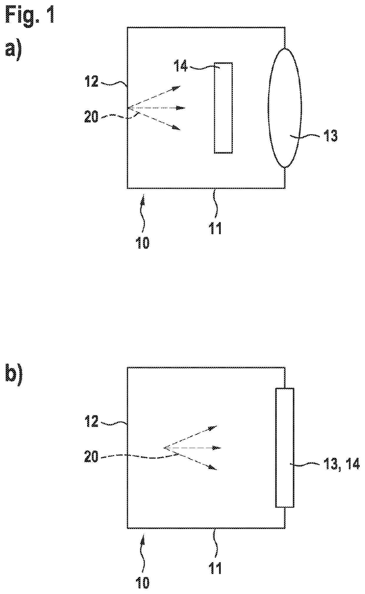
[0031]The 3-D lidar sensor 10 shown on the left side of FIG. 1 includes a laser beam source 11, which, as indicated by the different arrows, is configured to emit laser beams 20 in at least two spatial directions perpendicular to each other. In this manner, together with an optical receiver not shown here for the sake of simplifying the view, in particular, the surrounding area of a motor vehicle may be monitored. The 3-D lidar sensor includes a housing 12 and is situated, for example, on or in a body of a motor vehicle. Of course, it is equipped with an electric power supply, as well as with data transmission devices, in order to transmit measuring signals to a control device of the motor vehicle for further processing. In addition, a disk or lens 13 is situated on the housing, in order to allow laser beams 20 to emerge and possibly enter again. The present invention provides a further detection device 14, in this case, situated between laser beam source 11 and disk or lens 13, in ...


PUM

PropertyMeasurementUnit
wavelengthaaaaaaaaaa
photosensitive resistanceaaaaaaaaaa

Abstract

A 3-D lidar sensor, in particular, for motor vehicles, includes a laser beam source, an optical receiver and a scanning system for deflecting a laser beam generated by the laser beam source in two scanning directions perpendicular to each other; to increase the functionality, a further detection device for deviations from normal operation being provided in the 3-D lidar sensor. In addition, a corresponding method for operating the 3-D lidar sensor is provided.

Description

FIELD OF THE INVENTION[0001]The present invention relates to a 3-D lidar sensor, in particular, for motor vehicles, including a laser beam source, an optical receiver and a scanning system for deflecting a laser beam generated by the laser beam source in two scanning directions perpendicular to each other.BACKGROUND INFORMATION[0002]Such a 3-D lidar sensor is discussed in the publication DE 10 2015 200 224 A1 originating from the applicant. For example, laser beams of suitable intensity, having a wavelength between 850 and 1500 nm, are used in order to prevent danger to persons due to the laser beams. To deflect the laser beam, e.g., a micromirror actuator or a MEMS (microelectromechanical system) is used for guiding the laser beam in the desired direction. If a transit-time measurement of the laser beam, which is emitted, reflected at an object, and received again by the optical receiver, is also carried out, then a three-dimensional image of the surrounding area may be acquired an...

Claims


Application Information

Patent Timeline
Patent Type & Authority Patents(United States)
IPC IPC(8): G01S17/42G01S7/481G01S7/497G01S17/931
CPCG01S17/42G01S7/4813G01S7/497G01S17/931G01S7/4811G01S2007/4975
Inventor FREDERIKSEN, ANNETTEBUETTNER, AXELSCHWARZ, HANS-JOCHENSPARBERT, JANOSTRINSKY, JOEMSTOPPEL, KLAUSKAMIL, MUSTAFABOGATSCHER, SIEGWART
Owner ROBERT BOSCH GMBH
Why Eureka
Try Eureka