Vacuum pump protection against deposition byproduct buildup

a vacuum pump and byproduct technology, applied in the direction of machines/engines, mechanical equipment, coatings, etc., can solve the problems of reducing the performance and lifetime of the pump, and affecting the performance of the pump

a vacuum pump and byproduct technology, applied in the direction of machines/engines, mechanical equipment, coatings, etc., can solve the problems of reducing the performance and lifetime of the pump, and affecting the performance of the pump

US11031215B2Active Publication Date: 2021-06-08LAM RES CORP

Image

  • Vacuum pump protection against deposition byproduct buildup
  • Vacuum pump protection against deposition byproduct buildup
  • Vacuum pump protection against deposition byproduct buildup

Examples


Embodiment Construction

[0028]In the present disclosure, the terms “semiconductor wafer,”“wafer,”“substrate,”“wafer substrate,” and “partially fabricated integrated circuit” are used interchangeably. One of ordinary skill in the art would understand that the term “partially fabricated integrated circuit” can refer to a silicon wafer during any of many stages of integrated circuit fabrication. A wafer or substrate used in the semiconductor device industry typically has a diameter of 200 mm, or 300 mm, or 450 mm. The following detailed description assumes the present disclosure is implemented on a wafer. However, the present disclosure is not so limited. The work piece may be of various shapes, sizes, and materials. In addition to semiconductor wafers, other work pieces that may take advantage of the present disclosure include various articles such as printed circuit boards and the like.

INTRODUCTION

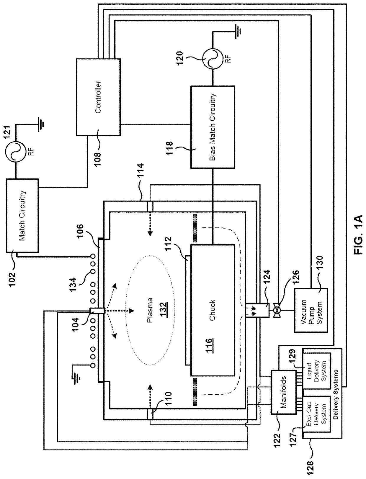
[0029]Conventionally, deposition and etch processes are performed on separate tools or platforms. For example, ...


PUM

PropertyMeasurementUnit
diameteraaaaaaaaaa
diameteraaaaaaaaaa
diameteraaaaaaaaaa

Abstract

A processing chamber such as a plasma etch chamber can perform deposition and etch operations, where byproducts of the deposition and etch operations can build up in a vacuum pump system fluidly coupled to the processing chamber. A vacuum pump system may have multiple roughing pumps so that etch gases can be diverted a roughing pump and deposition precursors can be diverted to another roughing pump. A divert line may route unused deposition precursors through a separate roughing pump. Deposition byproducts can be prevented from forming by incorporating one or more gas ejectors or venturi pumps at an outlet of a primary pump in a vacuum pump system. Cleaning operations, such as waferless automated cleaning operations, using certain clean chemistries may remove deposition byproducts before or after etch operations.

Description

INCORPORATION BY REFERENCE[0001]An Application Data Sheet is filed concurrently with this specification as part of the present application. Each application that the present application claims benefit of or priority to as identified in the concurrently filed Application Data Sheet is incorporated by reference herein in its entirety and for all purposes.BACKGROUND[0002]Vacuum pumps are widely used in semiconductor processing equipment to provide a clean and / or low-pressure environment in a processing chamber. Such vacuum pumps may be fluidly connected to the processing chamber to remove byproducts and unused etch and deposition precursors. Some vacuum pumps may be vulnerable to undesirable buildup of byproducts from mixing of etch and deposition precursors that can corrode or otherwise degrade the vacuum pumps over time.[0003]The background provided herein is for the purposes of generally presenting the context of the disclosure. Work of the presently named inventors, to the extent t...

Claims


Application Information

Patent Timeline
08 Jun 2021
Publication
US11031215B2
IPC
H01J37/32; H01L21/02; H01L21/311; H01L21/67; C23C16/02; C23C16/455; C23C16/44; H01L21/683
CPC
H01J37/32862; C23C16/0236; C23C16/4405; C23C16/45544; H01J37/32449; H01J37/32834; H01L21/0228; H01L21/02211
Inventors
DREWERY, JOHN STEPHEN; KAMP, TOM A.