Ultra-high speed vacuum pump system with first stage turbofan and second stage turbomolecular pump

一种涡轮分子泵、涡轮风扇的技术,应用在用于弹性流体的泵送装置的部件、泵、轴流泵等方向,能够解决购置成本再生或更换维护成本处理室污染、设计困难等问题

Inactive Publication Date: 2010-02-17
FERMI RESEARCH ALLIANCE LLC
View PDF5 Cites 0 Cited by
  • Summary
  • Abstract
  • Description
  • Claims
  • Application Information

AI Technical Summary

Problems solved by technology

However, because their design becomes very difficult when scaling up to ultra-high pumping speeds, conventional turbomolecular pumps are designed for high compression ratios and only for moderate pumping speeds
Disadvantages of using turbomolecular pumps in these situations include: acquisition cost, need for bearing regeneration or replacement, maintenance costs such as bearing replacement, contamination of the process chamber

Method used


Image

  • Ultra-high speed vacuum pump system with first stage turbofan and second stage turbomolecular pump
  • Ultra-high speed vacuum pump system with first stage turbofan and second stage turbomolecular pump
  • Ultra-high speed vacuum pump system with first stage turbofan and second stage turbomolecular pump

Examples


Embodiment Construction

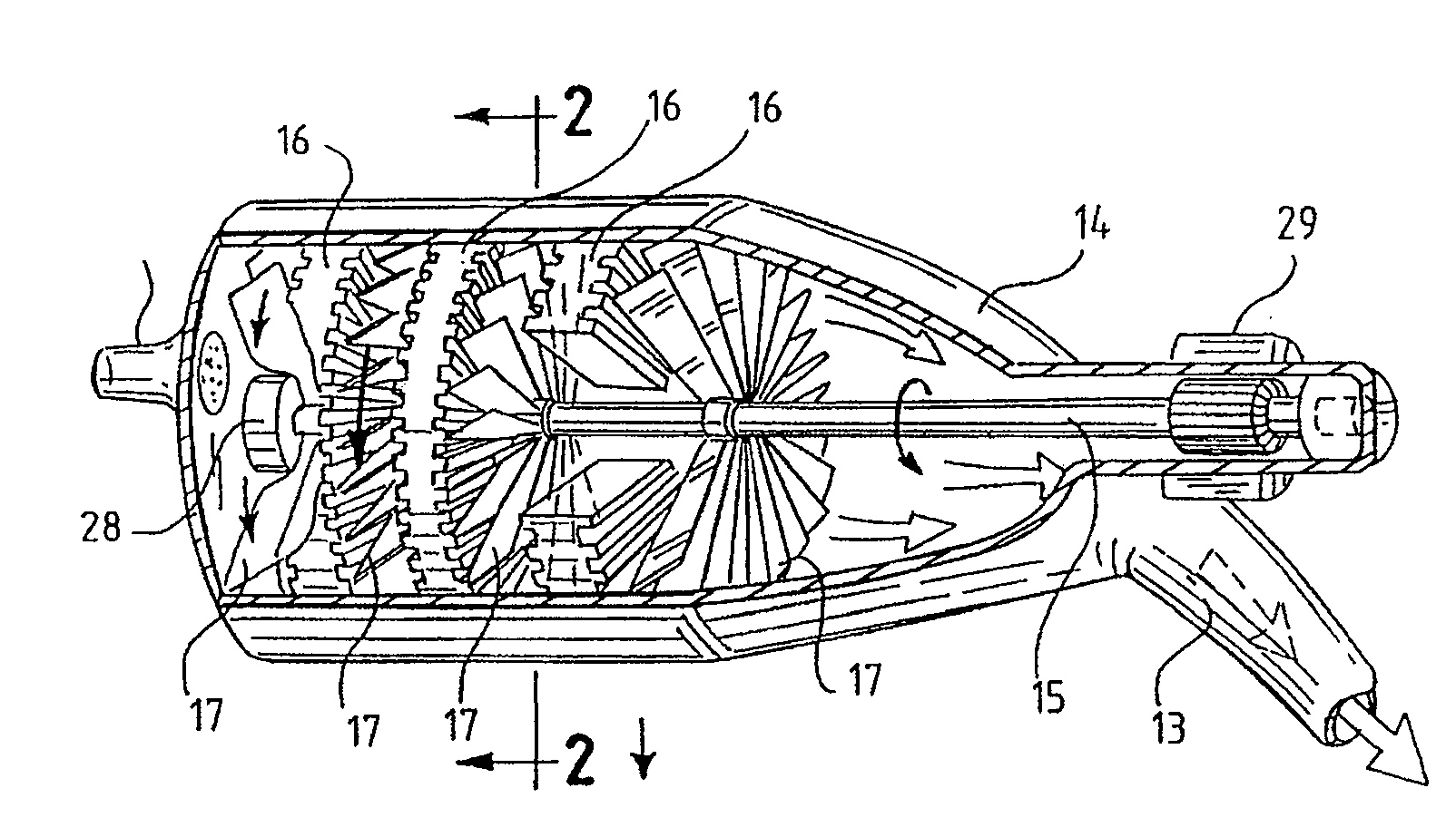
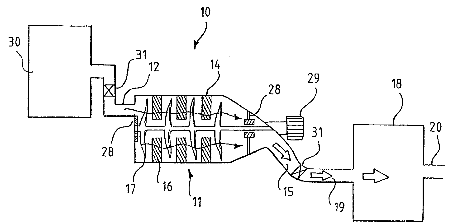
[0038] Such as figure 1 An embodiment of an ultrahigh-speed vacuum pump turbofan 11 is shown in , which is preferably used as an ultrahigh-speed input stage backed by a conventional turbomolecular pump. Turbofan 11 directs fluid flow into a turbofan inlet 12 and through a turbofan outlet 13 . Preferably, if Figure 4 and Figure 5 As shown, the outlet is in fluid communication with at least one additional turbofan or turbomolecular pump. Also preferably, as Figure 4 and Figure 5 As shown, the turbofan inlet 12 is in fluid communication with an evacuation or process chamber 30 . The turbofan 11 is characterized by a super high suction speed and a moderate compression ratio.

[0039] Typical pumping speeds are greater than 10,000 liters / second. More preferably, the pumping speed is 10,000 liters / second to 40,000 liters / second. In a preferred embodiment, the turbofan 11 has a suction speed of about 25,000 liters / second per 1.0 meter diameter of the turbofan.

[0040] S...


PUM


Abstract

An ultra-high speed vacuum pump evacuation system includes a first stage ultra-high speed turbofan and a second stage conventional turbomolecular pump. The turbofan is either connected in series to achamber to be evacuated, or is optionally disposed entirely within the chamber. The turbofan employs large diameter rotor blades operating at high linear blade velocity to impart an ultra-high pumpingspeed to a fluid. The second stage turbomolecular pump is fluidly connected downstream from the first stage turbofan. In operation, the first stage turbofan operates in a pre-existing vacuum, with the fluid asserting only small axial forces upon the rotor blades. The turbofan imparts a velocity to fluid particles towards an outlet at a high volume rate, but moderate compression ratio. The secondstage conventional turbomolecular pump then compresses the fluid to pressures for evacuation by a roughing pump.

Description

[0001] This invention was made with Government support under Contract No. DE-AC02-76CH03000 awarded by the United States Department of Energy. The government has certain rights in this invention. technical field [0002] The present invention relates to a vacuum pump for generating an ultra-high vacuum in an evacuated chamber. More specifically, the present invention relates to a vacuum pumping system including a first stage high speed turbofan and a second stage turbomolecular pump and a method of using the vacuum pumping system. Background technique [0003] Turbomolecular pumps (TMP; also sometimes referred to as turbopumps) are widely used to generate ultra-high vacuum in evacuated chambers. Vacuum pumps generally include turbomolecular pumps, drag pumps, centrifugal pumps, diffusion pumps, cryopumps, titanium sputter pumps, getter pumps, and the like. In general, turbomolecular pumps are used to pump gases, such as at 10 -8 Pa(10 -10 Torr) range, compressed to a pre...

Claims


Application Information

Patent Timeline
Patent Type & Authority Patents(China)
IPC IPC(8): F04D19/04F04D29/056F04D29/048
CPCF04D19/046F04D19/042
Inventor 汉斯·约斯特莱恩
Owner FERMI RESEARCH ALLIANCE LLC
Why Eureka
Try Eureka