Information display system for a vehicle

a technology for information display and vehicles, applied in the direction of cooling/ventilation/heating modifications, instruments, optics, etc., can solve the problem of generating a substantial amount of heat, and achieve the effect of limiting the play of pins and enhancing the cooling of display devices

Active Publication Date: 2021-07-20
MAGNA ELECTRONICS INC
View PDF15 Cites 0 Cited by
  • Summary
  • Abstract
  • Description
  • Claims
  • Application Information

AI Technical Summary

Benefits of technology

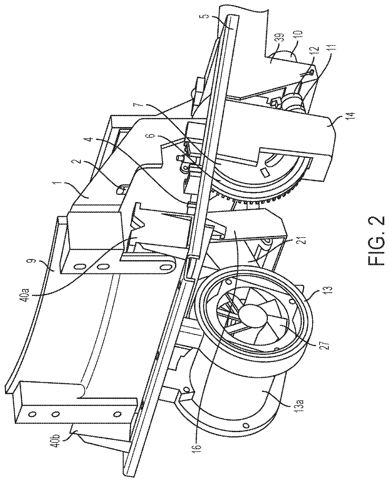
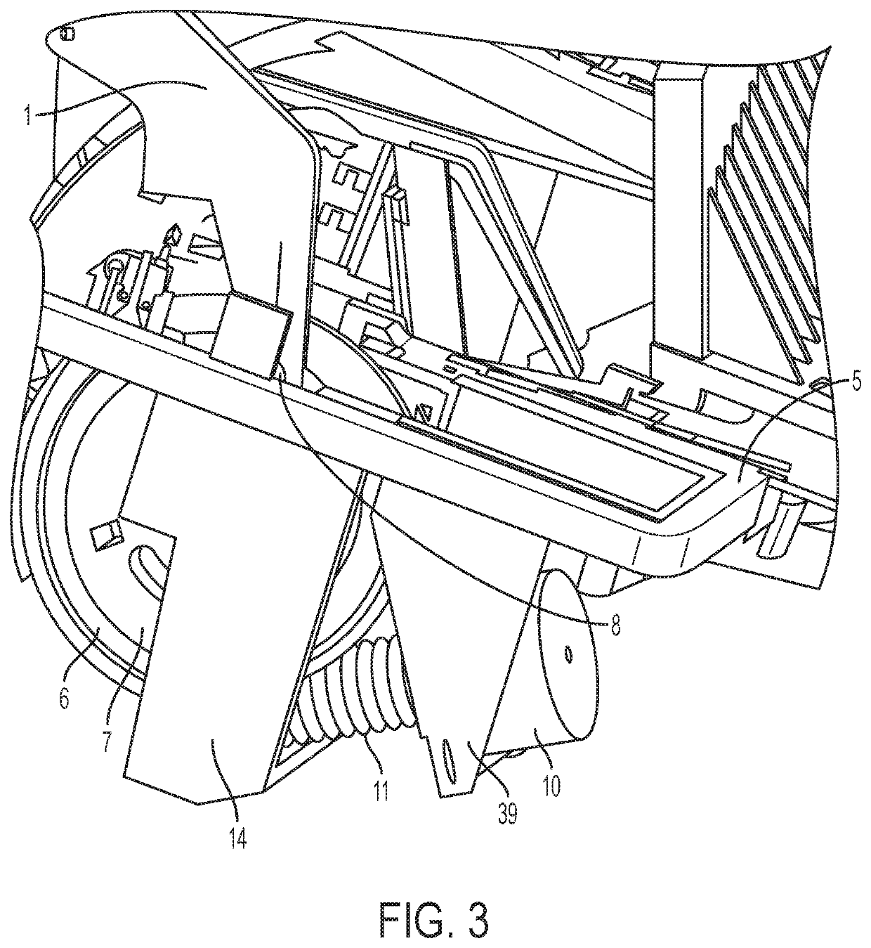
[0004]The present invention provides a driver assistance system or display system or imaging system for a vehicle that utilizes one or more cameras (preferably one or more CMOS cameras) to capture image data representative of images exterior of the vehicle, and provides a head up display that displays images or information for viewing by the driver of the vehicle. The head up display comprises a main mirror that is pivotable via actuation of a gear element, whereby a pin of a mounting arm of the mirror slides along a groove or channel of the gear element to cause pivotal movement of the mirror, with a biasing element that biases or urges the pin against a wall of the groove or channel to limit play of the pin and thus the mirror relative to the base plate. The gear element may also be tensioned towards engagement with teeth of a drive gear of a motor, to further limit play of the gear element and thus the mirror. The head up display includes a display screen holder that is pivotally attached at the base plate via a hook and clasp configuration. The head up display also includes a cooling device that has a cooling body, which provides enhanced cooling of the display device via a cooling body received at a cooling can housing attached at the display screen backlight, with the folded configuration of a heat plate in the can housing cooling the ends of the heat plate and cooling the cooling body that receives the ends of the heat plate.

Problems solved by technology

Such displays typically generate a substantial amount of heat that makes passive or active cooling necessary.

Method used


Image

  • Information display system for a vehicle
  • Information display system for a vehicle
  • Information display system for a vehicle

Examples


Embodiment Construction

[0052]A vehicle vision system and / or driver assist system and / or object detection system and / or alert system operates to capture images exterior of the vehicle and may process the captured image data to display images and to detect objects at or near the vehicle and in the predicted path of the vehicle, such as to assist a driver of the vehicle in maneuvering the vehicle in a rearward direction. The vision system includes an image processor or image processing system that is operable to receive image data from one or more cameras and provide an output to a display device for displaying images representative of the captured image data. The vision system provides a display, such as a rearview display or a top down or bird's eye or surround view display or the like, for viewing by the driver of the vehicle.

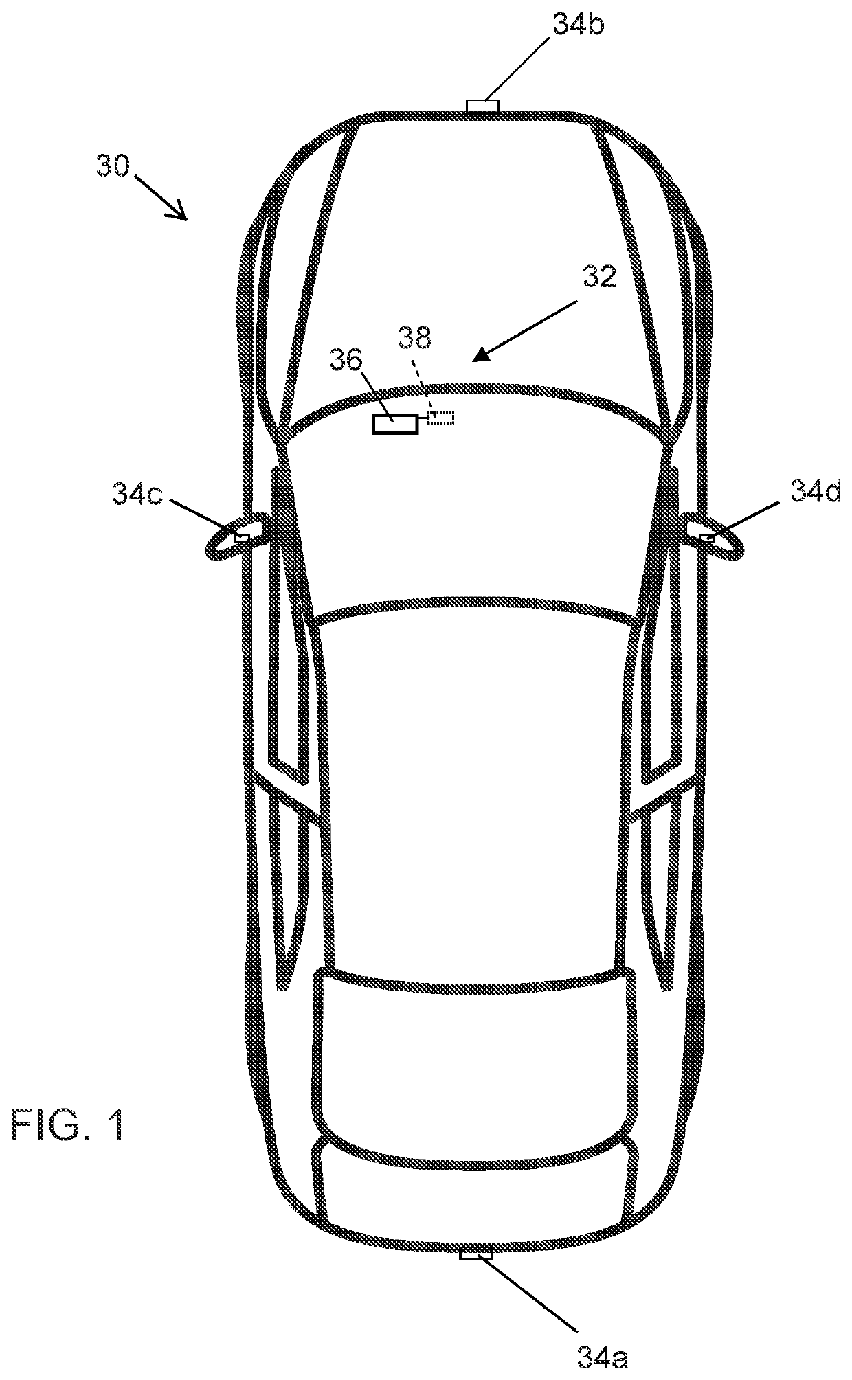
[0053]Referring now to the drawings and the illustrative embodiments depicted therein, a vehicle 30 includes an imaging system or vision system or display system 32 that includes a d...


PUM


Abstract

A display system of a vehicle includes a display device disposed in the vehicle and operable to display heads up information for viewing by a driver of the vehicle. The display device includes a mirror, a display screen and a cooling device. The mirror is pivotally mounted at a base plate and is pivotable via a pin of a mounting arm of the mirror moving along a spiral groove of a gear element when the gear element is rotated. The pin is urged towards a side wall of the spiral groove to limit play of the mirror relative to the base plate.

Description

CROSS REFERENCE TO RELATED APPLICATION[0001]The present application claims the filing benefits of U.S. provisional application Ser. No. 62 / 295,571, filed Feb. 16, 2016, which is hereby incorporated herein by reference in its entirety.FIELD OF THE INVENTION[0002]The present invention relates generally to a vehicle vision and display system for a vehicle and, more particularly, to a vehicle system that utilizes one or more cameras at a vehicle and that displays images for viewing by the driver of the vehicle.BACKGROUND OF THE INVENTION[0003]Use of imaging sensors in vehicle imaging systems is common and known. Examples of such known systems are described in U.S. Pat. Nos. 5,949,331; 5,670,935 and / or 5,550,677, which are hereby incorporated herein by reference in their entireties. It is also known to provide a display in the vehicle for displaying images for viewing by a driver of the vehicle during operation of the vehicle. Known automotive head up displays typically have a foldable m...

Claims


Application Information

Patent Timeline
Patent Type & Authority Patents(United States)
IPC IPC(8): G02B27/01H05K7/20
CPCG02B27/0101G02B27/01G02B27/0149H05K7/20163G02B2027/014G02B2027/0138G02B2027/0154
Inventor KUNZE, NORBERT
Owner MAGNA ELECTRONICS INC
Why Eureka
Try Eureka