Tools, systems, and methods for locating hidden studs and identifying angles on a finished wall

a technology of hidden studs and angles, applied in wave based measurement systems, instruments, reradiation, etc., can solve the problems of difficult or impossible visual identification of the location of the studs or ceiling joists supporting the drywall, and achieve the effect of quick and easy identification of the location of adjacent studs and quick and easy identification of the location

Active Publication Date: 2021-09-07
BERNSEN COLLIN D
View PDF22 Cites 0 Cited by
  • Summary
  • Abstract
  • Description
  • Claims
  • Application Information

AI Technical Summary

Benefits of technology

[0006]In some embodiments disclosed herein, a tool may assist a user in quickly and easily identifying a location of a stud in a finished wall. Once a first location of a stud has been identified, the tool may assist the user in quickly and easily identifying the location of adjacent studs. Furthermore, the tool may assist the user in identifying angles without the necessity of holding the tool on the wall once the studs have been located.

Problems solved by technology

Ideally, once the drywall has been painted, it is difficult or impossible to visually identify the location of the studs or ceiling joists supporting the drywall.

Method used


Image

  • Tools, systems, and methods for locating hidden studs and identifying angles on a finished wall
  • Tools, systems, and methods for locating hidden studs and identifying angles on a finished wall
  • Tools, systems, and methods for locating hidden studs and identifying angles on a finished wall

Examples


embodiment 1

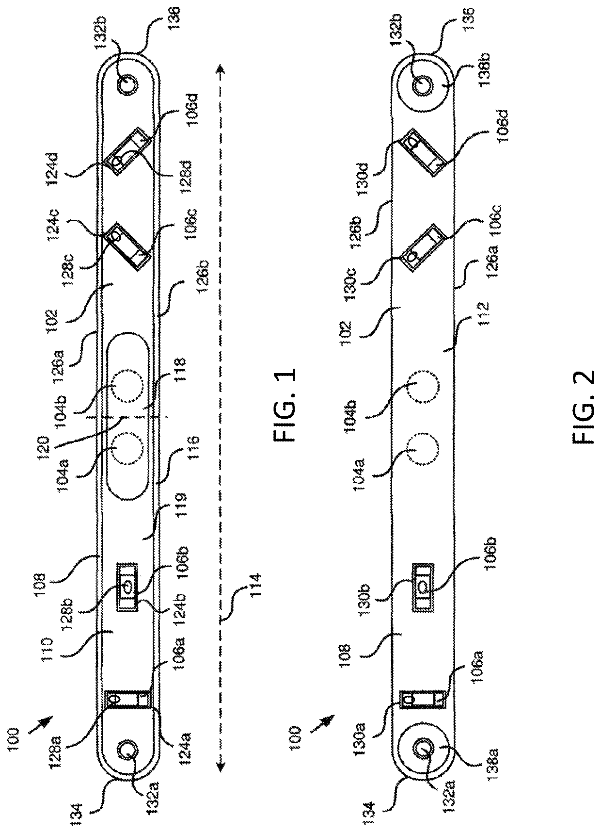
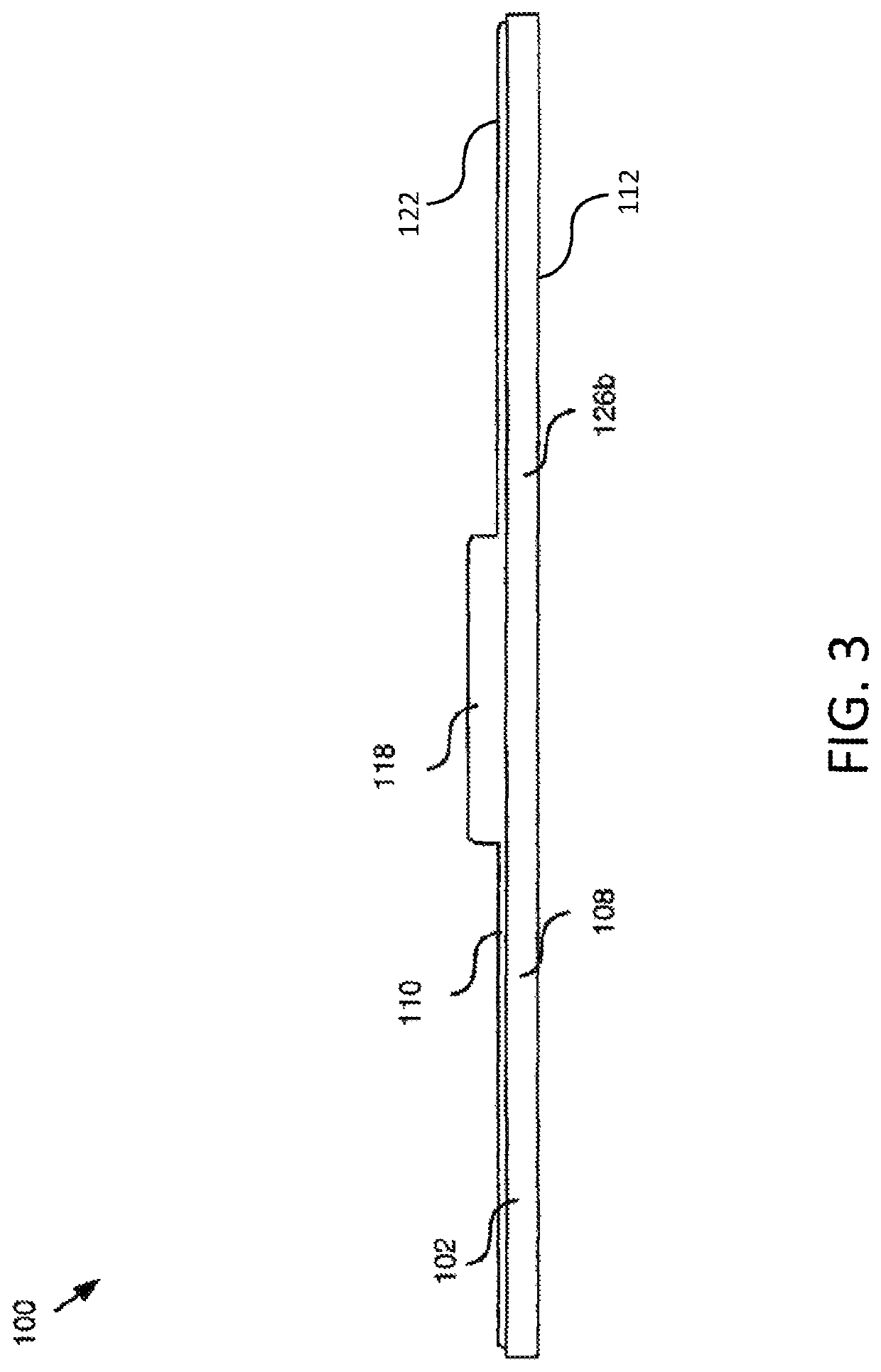
[0070] A tool to locate a hidden stud within a wall. The tool comprises an elongated housing having a generally planar contact surface and a viewing surface, at least one magnet, and at least one level secured to the housing such that the level is viewable from the viewing surface. The at least one magnet is secured to the housing such that a magnetic field associated with the at least one magnet extends outward from the contact surface. The magnetic field associated with the at least one magnet is sufficiently strong to cause a magnetic attraction between the tool and a metallic element in a vertical wall to maintain the tool on the vertical wall without external support.

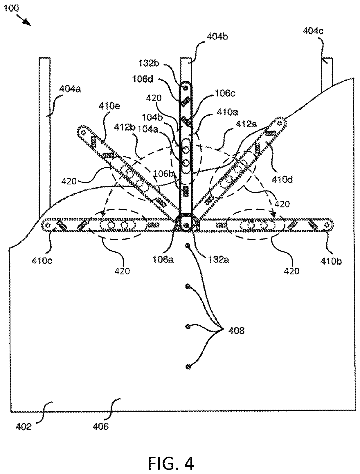
[0071]Embodiment 2: The tool of Embodiment 1, wherein the at least one level is oriented such that when a longitudinal edge of the housing is positioned at a selected orientation, the at least one level provides a visual indication that the longitudinal edge of the housing is oriented at the selected orientation.

[0...

embodiment 15

[0084] A method of forming a tool to locate a hidden stud within a wall. The method comprises forming an elongated housing having a generally planar contact surface and a viewing surface; securing at least one level to the housing such that the at least one level is viewable from the viewing surface; and securing at least one magnet to the housing such that a magnetic field associated with the at least one magnet extends outward from the contact surface. The magnetic field associated with the at least one magnet is sufficiently strong to cause a magnetic attraction between the tool and a metallic element in a vertical wall to maintain the tool on the vertical wall without external support.

embodiment 16

[0085] The method of Embodiment 15, wherein forming an elongated housing comprises injection molding at least one portion of the elongated housing.

[0086]Embodiment 17: The method of Embodiment 15 or Embodiment 16, wherein forming an elongated housing comprises securing a base member to a cover, wherein the elongated housing comprises the base member and the cover.

[0087]Embodiment 18: The method of any of Embodiments 15 through 17, wherein securing at least one level to the housing comprises disposing the at least one level within the housing.

[0088]Embodiment 19: A method comprising applying a force to the tool of Embodiment 1 to pass the generally planar contact surface thereof horizontally along a vertical wall. When the magnetic field associated with the at least one magnet causes a magnetic attraction between the tool and a metallic element in the vertical wall, the method includes withdrawing the applied force from the tool, such that the tool remains in place adjacent the verti...


PUM


Abstract

A tool, system, and method are disclosed for locating a hidden stud and identifying angles on a finished wall. The tool includes an elongated housing, at least one magnet, and at least one level. The housing has a generally planar contact surface disposed opposite a viewing surface. The at least one magnet is secured to the housing such that a magnetic field from the at least one magnet extends from the contact surface. The level is secured to the housing such that the level is viewable from the viewing surface. The at least one magnet, the level, and the housing are sized relative to each other such that a magnetic attraction between the at least one magnet and a metallic element in the wall is sufficient to maintain the tool on the wall without external support.

Description

TECHNICAL FIELD[0001]This invention relates to stud finders and more particularly relates to stud finders adapted to quickly locate adjacent studs and determine angles on finished walls.BACKGROUND[0002]In constructing buildings, walls are typically framed using a series of vertical studs. Studs may carry vertical structural loads or be non-loadbearing, such as in partition walls, which only separate spaces. Studs hold in place windows, doors, interior finish, exterior sheathing or siding, insulation and utilities and help give shape to a building. In the United States, studs are traditionally made of wood, usually nominally 2″×4″ or 2″×6″ dimensional lumber and typically placed 16 inches (406 mm) or 24 inches (608 mm) from one another, as measured from center-to-center.[0003]Often the interior finish includes sheets of drywall (also known as plasterboard, wallboard, or gypsum board) positioned adjacent to and covering the studs. The drywall is typically screwed or nailed to the stud...

Claims


Application Information

Patent Timeline
Patent Type & Authority Patents(United States)
IPC IPC(8): G01C9/24G01R33/00G01V3/165
CPCG01C9/24G01R33/0076G01V3/165G01V3/08G01C9/28
Inventor BERNSEN, COLLIN D.
Owner BERNSEN COLLIN D
Why Eureka
Try Eureka