Ut method of identifying a stuck joint

a technology of non-destructive evaluation and ut, applied in the direction of analysing solids using sonic/ultrasonic/infrasonic waves, instruments, measurement devices, etc., can solve the problems of stuck joints and particularly difficult to identify stuck joints using non-destructive evaluation, and achieve high gain a-scan, quick and easy identification of stuck joints

Active Publication Date: 2010-02-11
CUMBERLAND & WESTERN RESOURCES LLC
View PDF49 Cites 34 Cited by
  • Summary
  • Abstract
  • Description
  • Claims
  • Application Information

AI Technical Summary

Benefits of technology

[0011]In a stuck joint, the US transmitted beams do pass through the interface between the workpieces. The present invention is a method for quickly and easily identifying a stuck weld by looking for subtle variations in the high gain A-scan presentation of the reflected beam. In fact, the invention incorporates a novel technique of using a low gain US beam that is transmitted with the high gain US beam to identify the particular location on the high gain A-scan presentation in which to look for signs of a stuck joint. It is these subtle variations within a particular region that allow the present invention to correctly identify stuck joints versus good welds.
[0012]The present invention utilizes the secondary US beam to assist in identifying the subtle variations that distinguish a stuck joint. In fact, the secondary US beam is used to precisely locate the position on the high gain A-scan presentation that should be analyzed for the subtle variations. Thus, in addition to creating a high gain A-scan presentation associated with the primary US beam, the present invention also creates a low gain A-scan presentation associated with the secondary US beam.

Problems solved by technology

The cause of stuck joints is generally when there is insufficient heat at the welding interface to bring about nugget growth.
In the past, stuck joints have been particularly hard to identify using nondestructive evaluation (NDE) techniques.

Method used


Image

  • Ut method of identifying a stuck joint
  • Ut method of identifying a stuck joint
  • Ut method of identifying a stuck joint

Examples


Embodiment Construction

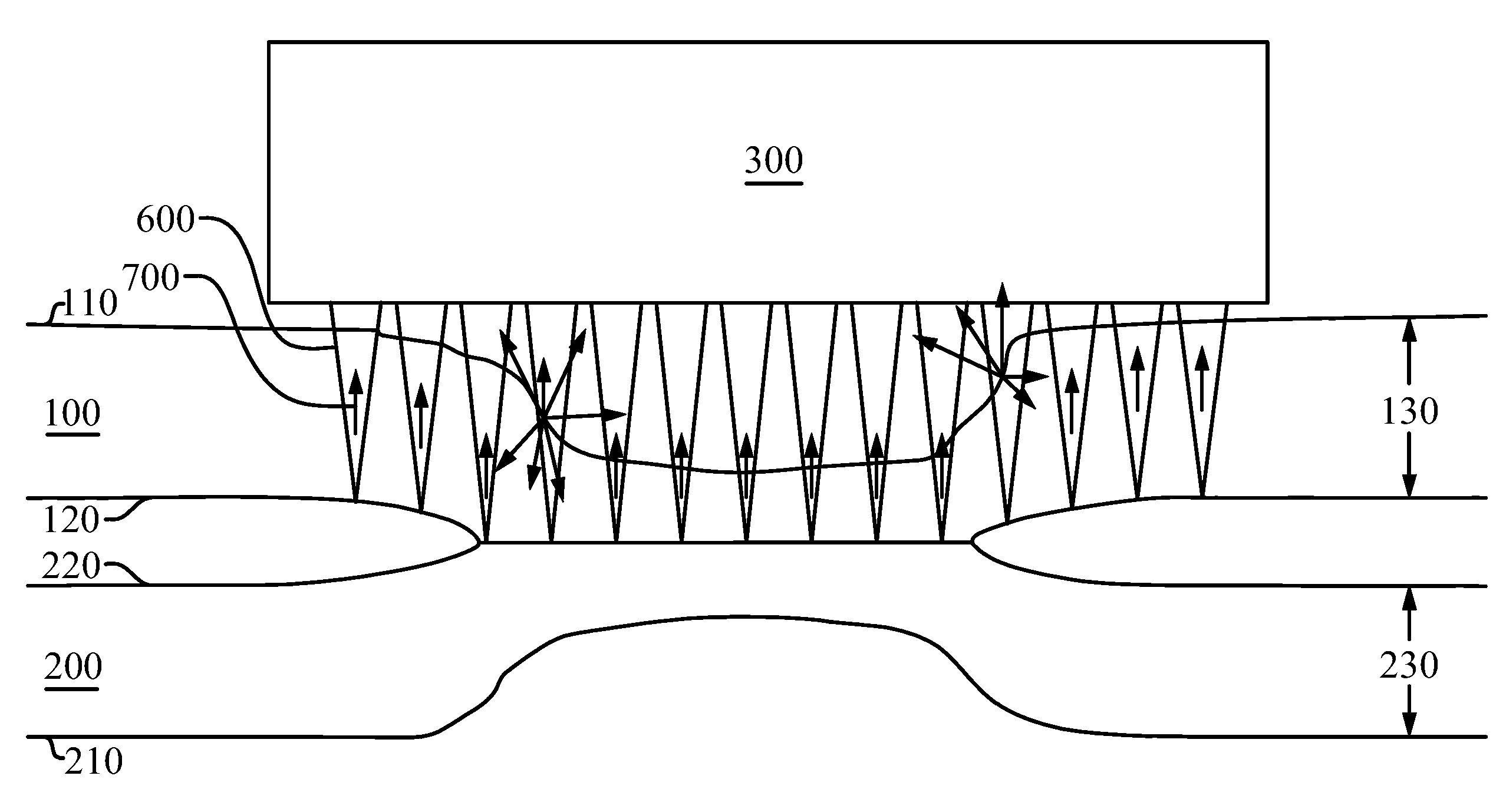
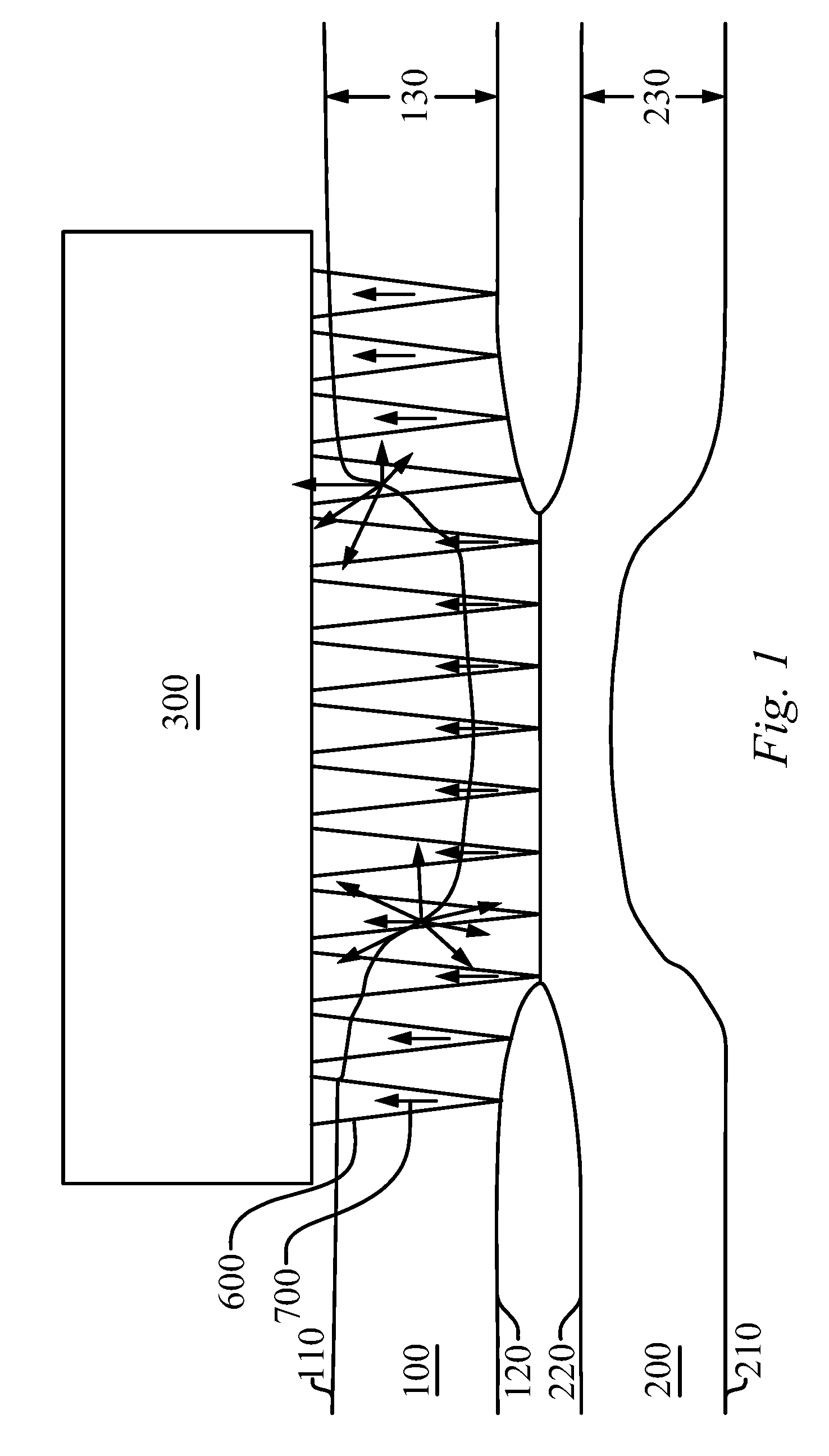
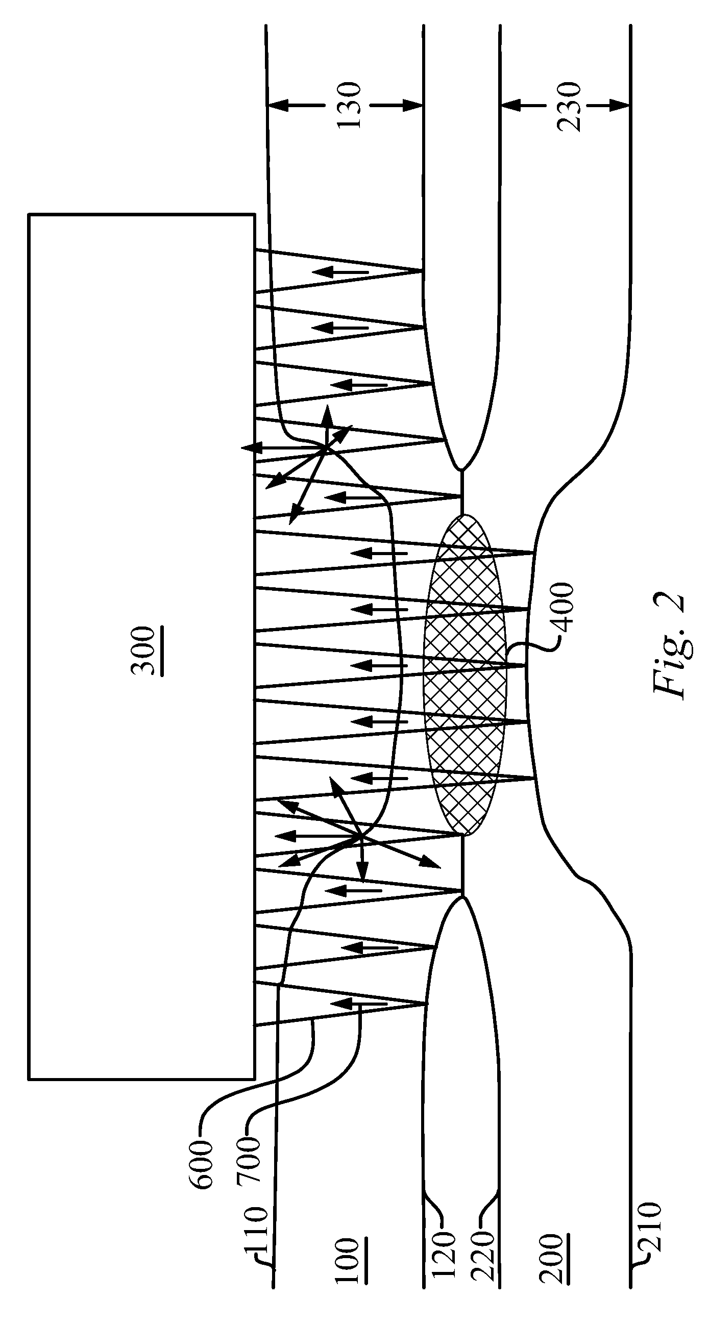
[0029]The UT method of identifying a stuck joint of the present invention enables a significant advance in the state of the art. The preferred embodiments of the method and system accomplish this by new and novel methods that are configured in unique and novel ways and which demonstrate previously unavailable but preferred and desirable capabilities. The description set forth below in connection with the drawings is intended merely as a description of the presently preferred embodiments of the invention, and is not intended to represent the only form in which the present invention may be constructed or utilized. The description sets forth the designs, functions, means, and methods of implementing the invention in connection with the illustrated embodiments. It is to be understood, however, that the same or equivalent functions and features may be accomplished by different embodiments that are also intended to be encompassed within the spirit and scope of the invention.

[0030]Prior to...


PUM

PropertyMeasurementUnit
diameteraaaaaaaaaa
ultrasonic testingaaaaaaaaaa
distanceaaaaaaaaaa

Abstract

An ultrasonic testing method to identify a stuck joint between two workpieces utilizing an ultrasonic probe to transmit ultrasonic (US) beams into the joint area and capture the associated US reflections. The method transmits two separate US beams fired in very close proximity to one another. The probe then captures a plurality of US reflections. The method looks for subtle variations in a high gain A-scan presentation of a high gain reflected beam, while using a low gain US beam to identify the particular region on the high gain A-scan presentation in which to look for signs of a stuck joint. Subtle variations within a particular region of the high gain A-scan presentation identify stuck joints. The method is applicable to metals and nonmetals and is not limited to fusion welding, but may also be used with solid state welds, brazed and soldered joints, and adhesively joined workpieces.

Description

STATEMENT REGARDING FEDERALLY SPONSORED RESEARCH OR DEVELOPMENT[0001]This invention was not made as part of a federally sponsored research or development project.TECHNICAL FIELD[0002]The present invention relates to the field of nondestructive evaluation, namely ultrasonic evaluation of joints to determine if a stuck, or cold, weld or bond is present.BACKGROUND OF THE INVENTION[0003]Sheet metal joining processes are widely used in many industries, such as the aerospace and automotive industries. Among these processes, resistance spot welding is the most common procedure used to join metal sheets because it has high process speed and is easily adopted in mass production lines; however, seam welding, weld bonding, adhesive joining, soldering, and brazing are gaining more widespread acceptance. The quality control of such joining processes is an important issue to manufacturers.[0004]The quality of such joints is affected by the joining process itself and the design of the joint. Many ...

Claims


Application Information

Patent Timeline
Patent Type & Authority Applications(United States)
IPC IPC(8): G01N29/04
CPCG01N29/069G01N2291/2672G01N2291/0234G01N29/11
Inventor SPENCER, ROGERLOZEV, MARGARITHUANG, TA-CHIEH
Owner CUMBERLAND & WESTERN RESOURCES LLC
Why Eureka
Try Eureka