
Screen printing press

a screen printing press and printing technology, applied in printing presses, rotary presses, printing, etc., can solve the problems of requiring precision mounting of registration pins to function, wear of crucial parts, and inaccurate screen registration, etc., to achieve fast and accurate registration, improve the accuracy of screen registration and mechanical features, and facilitate storage and display of burn units.

Active Publication Date: 2021-09-21
JURMAN GARY PAUL
View PDF7 Cites 2 Cited by
  • Summary
  • Abstract
  • Description
  • Claims
  • Application Information

AI Technical Summary

Benefits of technology

[0007]The present invention addresses the previously-mentioned deficiencies by providing a screen printing press with superior screen registration and mechanical features. The screen registration apparatus of the present invention allows a user to quickly and accurately register a screen in three axes of the clamping mechanism of the print head. Additionally, the base of the screen printing press provides for convenient storage and display of the burn unit. As such, the screen printing press provides a device which looks like a single integrated unit, but which in fact has the advantages of two separate elements which can either function together or be used separately.

Problems solved by technology

Problems exist in screen printing presses with respect to providing accurate screen registration when printing multiple colors.
While screen mounted registration systems exist, they suffer from wear of crucial parts and require precision mounting of registration pins to function.
The registration pins have a small surface area for contact, causing wear to have a more profound effect on registration.
Also, such registration pins must be precisely oriented in the x-y-z coordinate system or fail, causing greater accuracy requirements in the mounting process.
However, the performance of these presses can be degraded because they must necessarily balance the needs of competing functional requirements.
This approach can interfere with the placement of the substrate onto the printing platen, and also slow production of finished products.
Problems can also arise with the size of the press being too large for the available work space and storage area.

Method used


Image

  • Screen printing press
  • Screen printing press
  • Screen printing press

Examples


Embodiment Construction

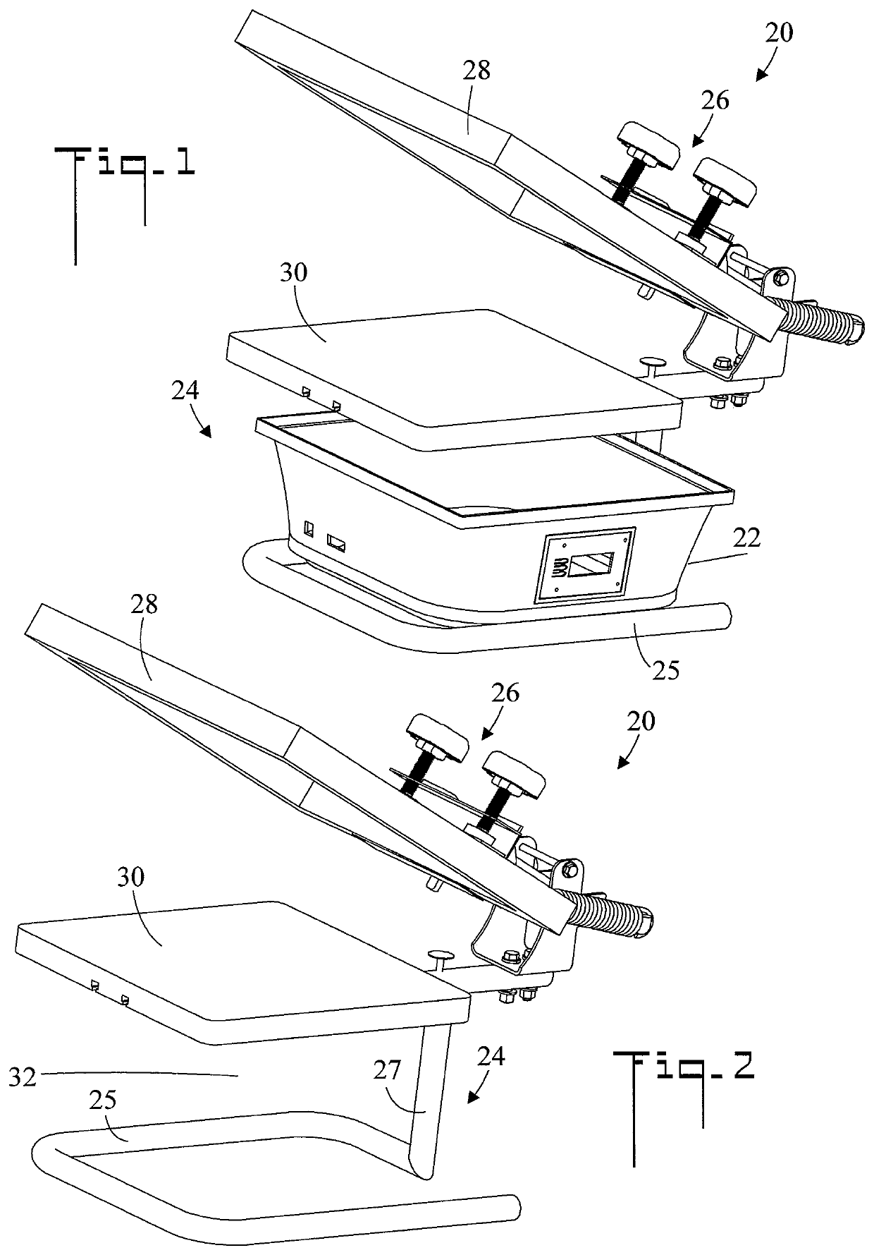
[0039]Referring initially to FIGS. 1 and 2, there are illustrated perspective views of a screen printing press 20 with and without a burn unit 22 installed respectively. Screen printing press 20 includes a base 24. A clamping mechanism 26 is connected to base 24. In the shown embodiment, clamping mechanism 26 is pivotally connected to base 24 so that it can be rotated to the shown up substrate loading position, or to the down (a) substrate printing position of FIG. 10) and (b) on-unit burning position of FIG. 17. A screen 28 is shaped and dimensioned to be received and clamped by clamping mechanism 26. A platen 30 which supports a substrate 500 to be printed (such as a T-shirt) is connected between base 24 and clamping mechanism 26 (refer also to FIG. 10).

[0040]Referring to FIG. 2, base 24 includes an open frame which defines a volume 32 which is shaped and dimensioned to receive burn unit 22, so that when burn unit 22 is placed within volume 32 burn unit 22 is visible as is shown i...


PUM


Abstract

A screen printing press includes a base and a clamping mechanism which is connected to the base. The clamping mechanism has a first member, a second member disposed perpendicular to the first member, and an edge. The clamping mechanism has X, Y, and Z axes, The screen has a first surface and a second surface perpendicular to the first surface. A protruding stop is disposed on at least one of the first surface and the second surface. The screen is positioned in the clamping mechanism so that the first surface abuts the first member, the second surface abuts the second member, and the protruding stop abuts the edge. The base includes an open frame which defines a volume which is shaped and dimensioned to receive a burn unit, so that when the burn unit is placed within the volume the burn unit is visible.

Description

CROSS REFERENCE TO RELATED APPLICATION[0001]This application is a Continuation of and claims the filing benefit under 35 U.S.C. § 120 of application Ser. No. 14 / 471,021, filed Aug. 28, 2014, which is hereby incorporated by reference. This application also claims the filing benefit under 35 U.S.C. § 119(e) of U.S. Provisional Application No. 61 / 882,322, filed Sep. 25, 2013, which is hereby incorporated by reference.TECHNICAL FIELD[0002]The present invention generally pertains to screen printing presses, and more particularly to a screen printing press which includes a registration system and method for accurately positioning a screen in the screen printing press.BACKGROUND OF THE INVENTION[0003]Screen printing presses are well known in the art. These devices utilize a screen to print an image on a substrate. The image is “burned” onto the screen using a positive transparency and a burn unit. Ink is then applied and passes through the screen and onto the substrate.[0004]Problems exist...

Claims


Application Information

Patent Timeline
Patent Type & Authority Patents(United States)
IPC IPC(8): B41F15/02B41F15/18B41F15/34
CPCB41F15/18B41F15/02B41F15/34B41F15/0818B41F15/36B41F15/10B41F15/08B41F15/12B41F15/0863
Inventor JURMAN, GARY PAUL
Owner JURMAN GARY PAUL
Learn More