Storage cabinet

a storage cabinet and upper cover technology, applied in the field of cabinets, can solve the problems of laborious opening or closing the upper cover, the arms of a person standing in front of the cabinet are not long enough to directly operate the cabinet, and the cabinet can barely be operated by a person standing, so as to simplify the structure of the upper cover and the cabinet body

Active Publication Date: 2021-10-12
NEW TEC INTEGRATION (XIAMEN) CO LTD
View PDF9 Cites 0 Cited by
  • Summary
  • Abstract
  • Description
  • Claims
  • Application Information

AI Technical Summary

Benefits of technology

[0013]Compared with the background art, this technical solution has the following advantages:
[0015]When the upper cover is opened or closed, the upper cover connector rotates synchronously, the swing piece swings and provides space to the pneumatic bar, the pneumatic bar extends or retracts correspondingly, and the pneumatic bar can stably support the upper cover. In this way, the upper cover is stably opened or closed.
[0017]3. The upper cover is not directly pivotally connected to the cabinet body, but the cabinet body connector is pivotally connected to the upper cover connector. Therefore, a structure of the upper cover and the cabinet body is simplified.

Problems solved by technology

Therefore, a degree to which the upper cover rotates when being opened or closed is large, and opening or closing the upper cover is laborious.
Even when a cabinet is small, the cabinet can barely be operated by a person standing in front of the cabinet.
When a cabinet is large, the arms of a person standing in front of the cabinet are not long enough to directly operate the cabinet.
Instead, the person needs to move to a side of the cabinet to open or close the upper cover, and therefore the operation is not convenient.
If the upper cover is accidently touched, the support rod easily falls down, and the upper cover falls down too due to the lack of support.
The upper cover can hurt the user when falling, or an impact force of the falling upper cover can be great enough to cause a connection between the upper cover and the cabinet to break.

Method used


Image

  • Storage cabinet
  • Storage cabinet
  • Storage cabinet

Examples


embodiment 1

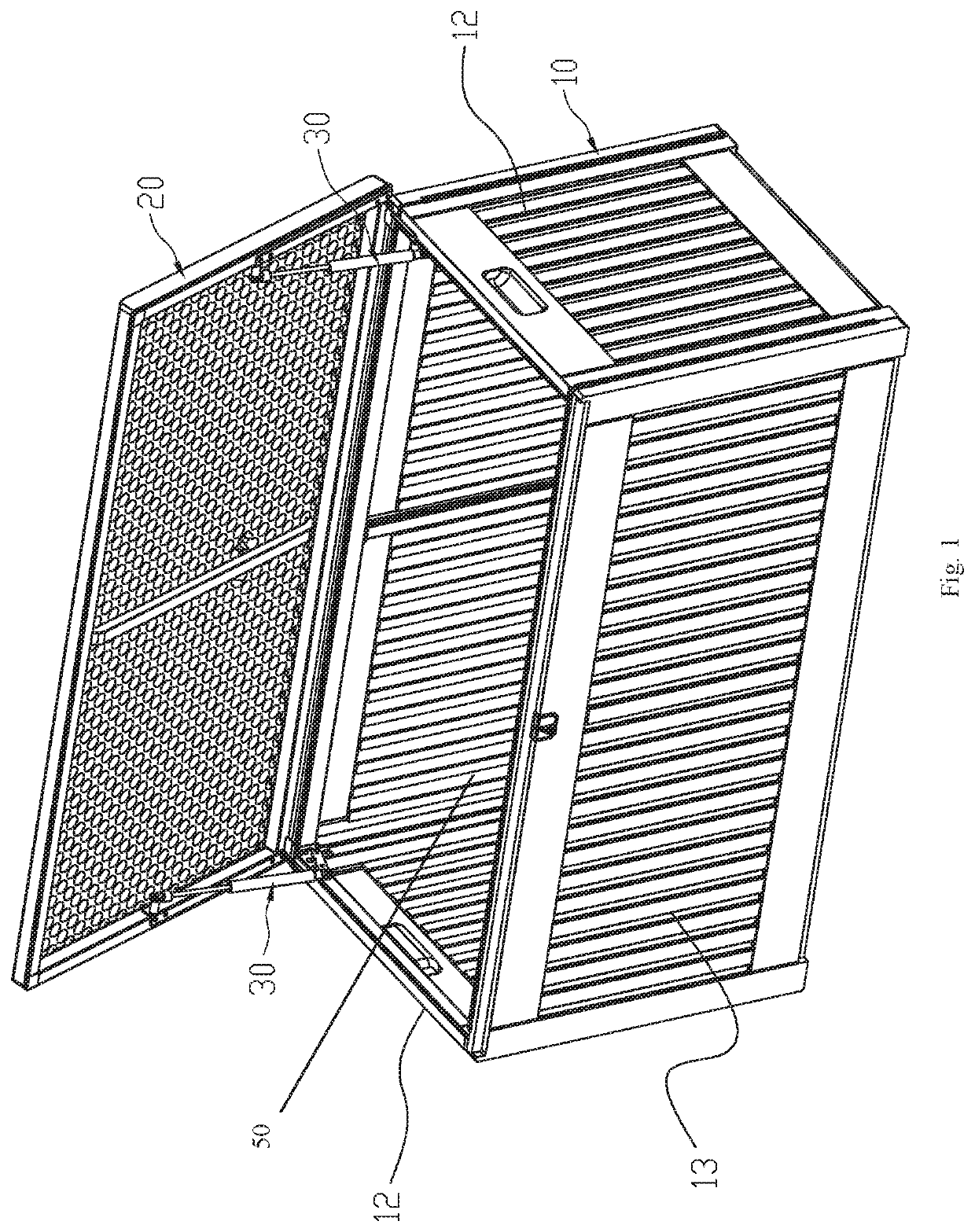
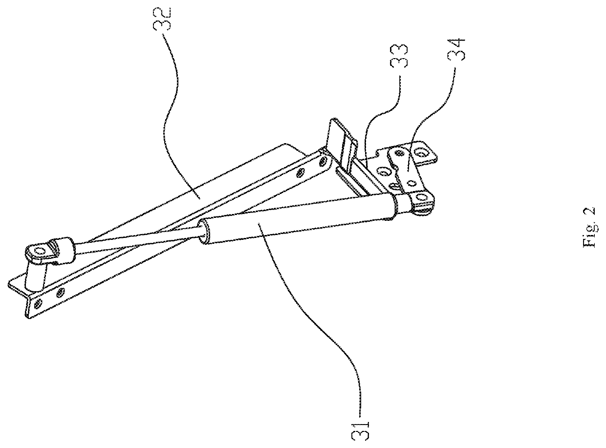
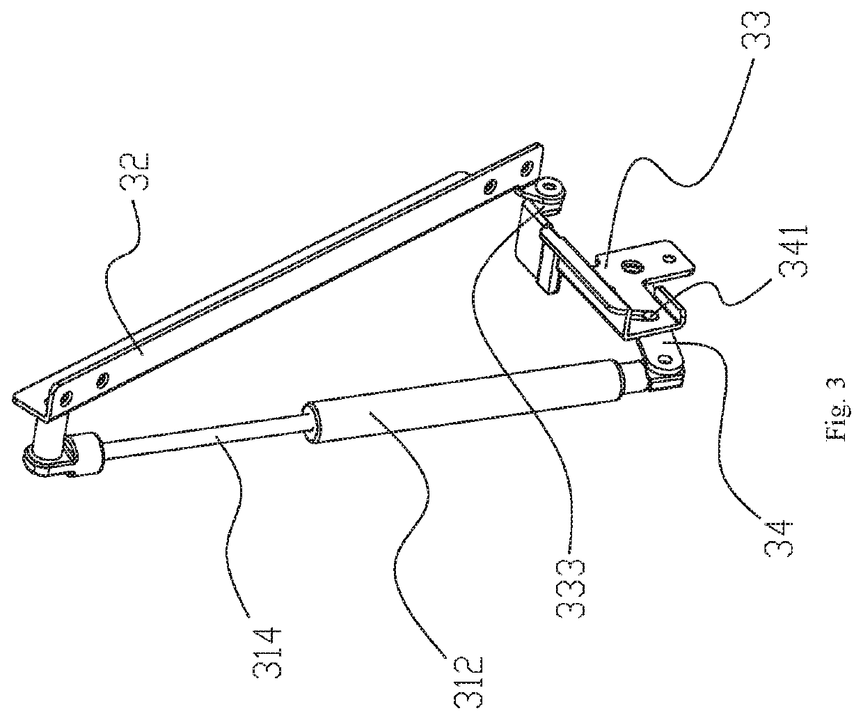
[0024]Referring to FIGS. 1-5, a storage cabinet with a positionable upper cover comprises a cabinet body 10 with a top opening 50, an upper cover 20 configured to cover the top opening 50, and two support elements 30. The cabinet body 10 comprises a bottom board 11, a left board 12, a right board 12, a front board 13, and a rear board 14. The two support elements 30 are respectively symmetrically disposed on a left side and a right side of the cabinet body 10. Each of the two support elements 30 is connected between the upper cover 20 and the cabinet body 10. Each of the two support elements 30 comprises a pneumatic bar 31, an upper cover connector 32, a cabinet body connector 33, and a swing piece 34. The upper cover connector 32 is fixedly connected to a side of the upper cover 20, and the cabinet body connector 33 is fixedly connected to a side of the cabinet body 10. A first end of the upper cover connector 32 is pivotally connected to a first end of the cabinet body connector 3...


PUM


Abstract

A storage cabinet a cabinet body with a top opening, an upper cover, and two support elements is provided. Each of the two support elements is connected between the upper cover and the cabinet body. Each of the two support elements comprises a pneumatic bar, an upper cover connector, a cabinet body connector, and a swing piece. The upper cover connector is connected to a side of the upper cover, and the cabinet body connector is connected to a side of the cabinet body. A first end of the upper cover connector is pivotally connected to a first end of the cabinet body connector, and a first end of the swing piece is pivotally connected to the cabinet body connector. Two ends of the pneumatic bar are respectively connected to a second end of the swing piece and a second end of the upper cover connector.

Description

RELATED APPLICATIONS[0001]This application claims priority to Chinese Patent Application 201920206355.4, filed on Feb. 18, 2019, which is incorporated herein by reference.FIELD OF THE DISCLOSURE[0002]The present disclosure relates to a cabinet, and in particular relates to a storage cabinet having a positionable upper cover.BACKGROUND OF THE DISCLOSURE[0003]Storage cabinets, also referred to herein as cabinets, are usually a hollow, rectangular-shaped or square-shaped box structure, and a top surface of the cabinets is configured to be opened and closed freely, thereby functioning as an upper cover. Traditional storage cabinets comprise no position assemblies for keeping the upper cover at a set position upon being opened. When the upper cover is opened, the upper cover is rotated to a back side of the cabinets and hangs down naturally. Therefore, a degree to which the upper cover rotates when being opened or closed is large, and opening or closing the upper cover is laborious. Even...

Claims


Application Information

Patent Timeline
Patent Type & Authority Patents(United States)
IPC IPC(8): E05F5/10
CPCE05F5/10E05Y2900/20A45C5/00A45C5/03A45C5/04E05F1/1292E05Y2201/478E05Y2900/602
Inventor LENG, LUHAO
Owner NEW TEC INTEGRATION (XIAMEN) CO LTD
Why Eureka
Try Eureka