An operating mechanism and a locomotive using the operating mechanism

An operating mechanism and operating lever technology, applied in the direction of the power device inside the switch, etc., can solve the problems of unstable closing retention force, reduced closing reliability and stability, and shortened service life of the electromagnetic coil, avoiding the The closing holding force is unstable, improving the reliability and stability, and the effect of closing the holding state is stable

Active Publication Date: 2019-06-11
STATE GRID CORP OF CHINA +2
View PDF6 Cites 0 Cited by
  • Summary
  • Abstract
  • Description
  • Claims
  • Application Information

AI Technical Summary

Problems solved by technology

However, in the closing and holding state, the electromagnetic coil of the electromagnet in the operating mechanism needs to be continuously charged to ensure sufficient electromagnetic attraction between the magnet and the piston, and because the electromagnetic coil is inside the outer iron core, the outer iron core will hinder The heat dissipation of the electromagnetic coil, so the heat generation of the continuously charged electromagnetic coil will be larger, which will not only make the magnetism of the electromagnet unstable, but also shorten the service life of the electromagnetic coil when the electromagnetic coil continues to generate heat and cannot dissipate heat in time , or even burned out, so the operating mechanism that uses the electromagnet and permanent magnet to maintain the closed state is prone to unstable closing force during use, resulting in reduced reliability and stability of closing

Method used


Image

  • An operating mechanism and a locomotive using the operating mechanism
  • An operating mechanism and a locomotive using the operating mechanism
  • An operating mechanism and a locomotive using the operating mechanism

Examples


Embodiment Construction

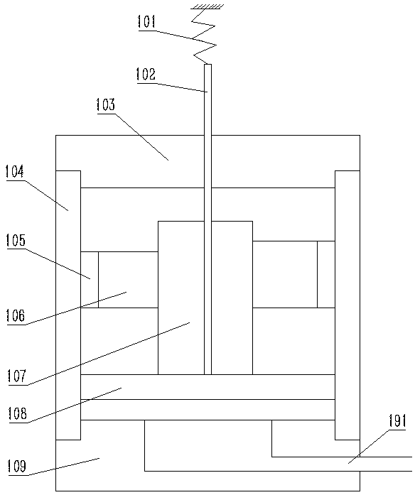
[0023] Embodiment 1 of locomotive among the present invention: as figure 1 As shown, the locomotive includes the locomotive and the operating mechanism assembled on it. The operating mechanism belongs to the field of high-voltage switches, and can be applied not only to the on-board switch control on the locomotive, but also to other operating systems on the car. The operating mechanism includes a cylinder body 104, an upper end cover 103 and a lower end cover 109 fixedly connected to a main cylinder body, the main cylinder body extends along the opening and closing direction, and a piston 108 is installed in the cylinder body 104 to move up and down. The up and down direction is also the opening and closing direction set by the operating mechanism. The piston 108 divides the inner cavity of the main cylinder into an upper closing chamber and a lower opening chamber. At the closing end, the lower end cover 109 is at the opening end of the cylinder body 104 . On the lower end ...


PUM


Abstract

The invention discloses an operating mechanism and a locomotive using the same. The magnets of the operating mechanism are permanent magnets; the permanent magnets are used for acting on a piston through an independent permanent magnetic force or a resultant force of the permanent magnetic force and air pressure in a switching-off cavity when switching on is performed in place, so that the piston can keep abutting against the switching-on end of a main cylinder. After the operating mechanism performs in-place switching on, the permanent magnets can act on the piston through the permanent magnetic force or the resultant force of the permanent magnetic force and air pressure in the switching-off cavity, so that an operating rod can be kept in a switching-on state under the driving of the piston. Compared with a structure in which an electromagnetic force provided by electromagnets is needed when an operating rod is kept in a switching-on state, the operating mechanism of the invention does not need the help of electromagnets when being in the switching-on state, and therefore, problems of instability of a switching-on retention force and high possibility of being burnout of electromagnetic coils which are brought about by continuous power supply of the electromagnetic coils of the electromagnets can be avoided, and the switching-on retention state of the operating mechanism can be stable.

Description

technical field [0001] The invention relates to an operating mechanism and a locomotive using the operating mechanism. Background technique [0002] At present, the operating mechanisms used in high-voltage switches and related fields are mostly spring operating mechanisms and permanent magnet operating mechanisms, but spring operating mechanisms have complex structures, many potential failure points, and low mechanical life, so it is difficult to meet the requirements of long life; permanent magnet operation The structure of the mechanism is simple and the mechanical life is long. However, the permanent magnet operating mechanism needs a large-capacity power supply when it operates. The moving mechanism has certain limitations in the process of use. In locomotive on-board equipment and other special occasions, the operating mechanism is required to have a long life and a small power supply capacity, so the pneumatic operating mechanism is the best choice. The pneumatic mec...

Claims


Application Information

Patent Timeline
Patent Type & Authority Patents(China)
IPC IPC(8): H01H3/24H01H3/28
CPCH01H3/24H01H3/28
Inventor 王帮田纪江辉王小丽张鹏王金雷杨思亮李文峰李燕燕赵玉芝
Owner STATE GRID CORP OF CHINA
Why Eureka
Try Eureka