
Irrigation assembly

a technology of irrigation and assembly, which is applied in the field of irrigation assembly, can solve the problems of inconvenience, unusability, and/or waste, and achieve the effects of effective cleaning, disinfection and/or promotion and maintenance of nasal hygien

Active Publication Date: 2021-11-23
PREVA
View PDF83 Cites 0 Cited by
  • Summary
  • Abstract
  • Description
  • Claims
  • Application Information

AI Technical Summary

Benefits of technology

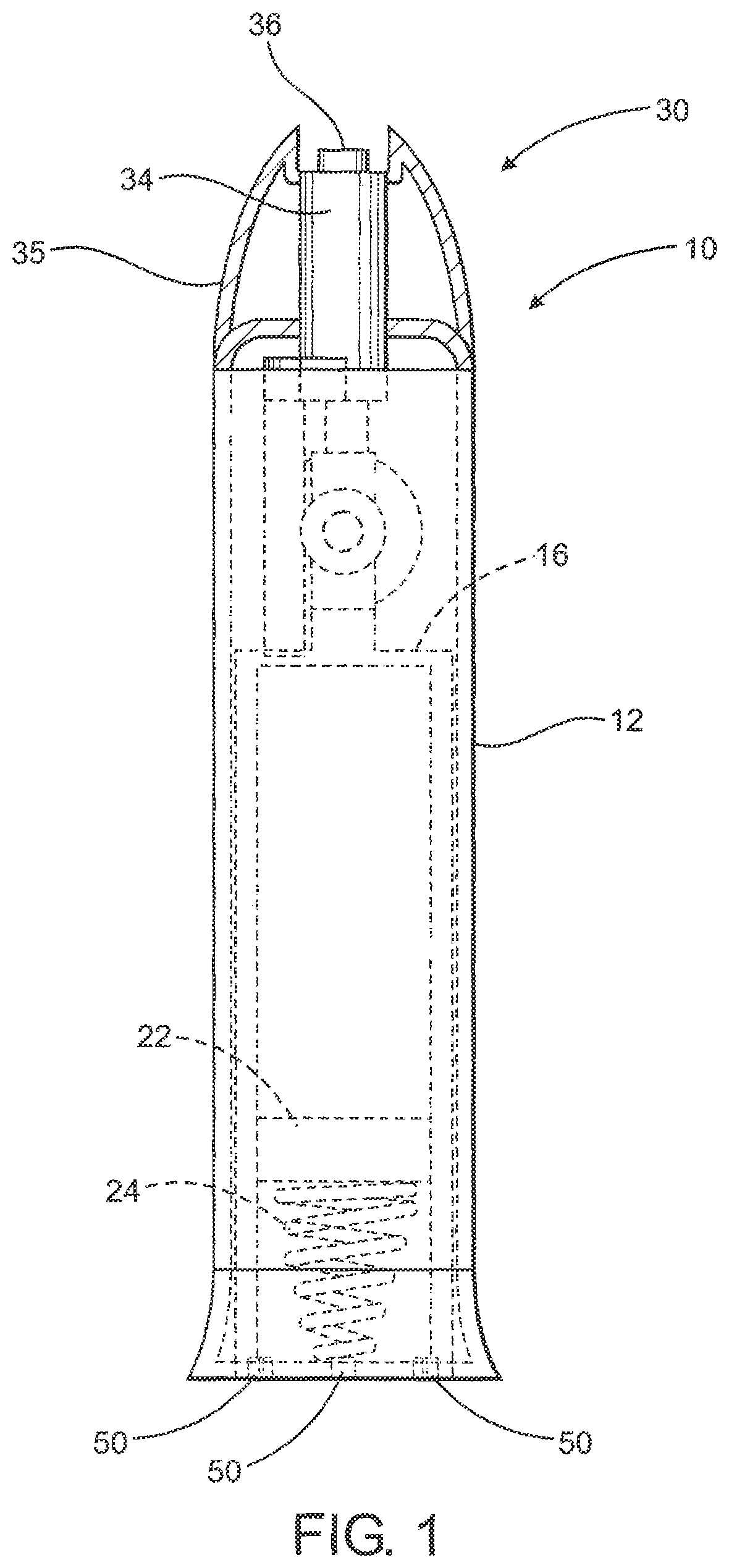
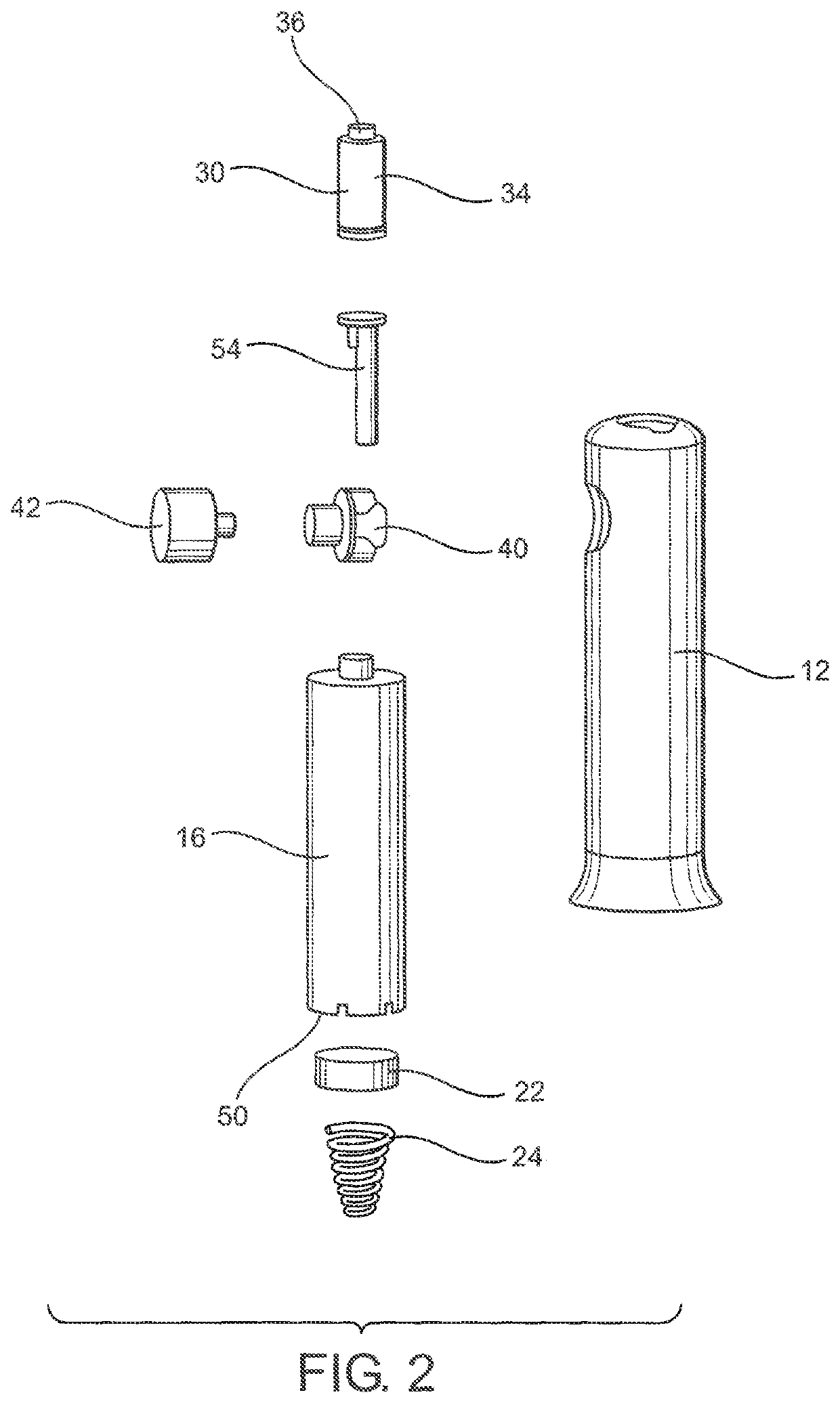
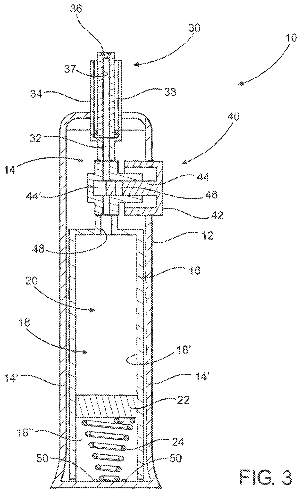
[0013]The present invention is directed to an assembly structured for the concurrent irrigation and aspiration of an individual's nasal cavity and passages in order to promote and maintain better nasal hygiene by effectively cleaning, disinfecting and / or medicating the nasal cavity and passages. More specifically, the irrigation assembly comprises a housing having an at least partially hollow interior of sufficient dimension and configuration to include a supply container therein. The supply container may be in a tubular or barrel like configuration at least partially similar in shape, structure and operation to the barrel of a syringe. Of course, additional shapes, including a square, triangle, oval or other shape may be equally effective.
[0014]Moreover, the interior of the supply container defines a chamber in which irrigating fluid is removably retained for eventual delivery to the nasal cavity. In addition, at least one embodiment comprises the supply container being prefilled or preloaded with an irrigating fluid which may affect the cleaning, as well as the disinfecting, of the nasal cavity and passages, thereby facilitating the maintenance of healthful nasal hygiene. The aforementioned disinfecting capabilities can be accomplished by formulating the irrigating fluid to include an appropriate disinfecting agent such as, but not limited to, hydrogen peroxide, acetic acid, a chlorine based substance, etc. Similarly, appropriate medication may be included in or define the irrigating fluid. Accordingly, a variety of different conditions including, but not limited to, infections, allergies, etc. can be effectively treated and / or prevented through the utilization of the irrigation assembly of the present invention, in order to establish and maintain proper nasal hygiene.
[0016]The concurrent irrigation and aspiration of each nostril serves to prevent flooding of the nasal cavity, wherein such flooding is frequently recognized as being uncomfortable, messy, and / or unnecessary to accomplish beneficial nasal hygiene. Flooding of the nasal cavity is also selectively prevented by regulating the volume and / or the pressure of the irrigating fluid being delivered. Moreover, in order to accurately regulate the irrigating fluid in the manner described, at least one embodiment of the irrigation assembly may include an alarm, recorded voice prompt or other appropriate indicating facilities operative to provide a clear indication to a user, as to the volume, quantity, etc. of the irrigating fluid being administered, during each irrigating session.
[0017]One additional feature of the present invention includes each of a plurality of dispensing nozzles being formed in the outer or “delivery end” of the applicator. Moreover, each nozzle is disposed at preferably an angle of 5-45 degrees relative to the longitudinal center axis of the applicator. By virtue of this preferred angular orientation, the irrigating fluid or liquid will be dispensed concurrently from each of the dispensing nozzles in a predetermined dispensing pattern. In turn, a substantially or at least partially swirling or “vortex” flow of the irrigating fluid will occur as it exits the nozzles and impinges onto the interior surfaces of the nostril in which the applicator is inserted. Such a “vortex” configuration of the dispensing pattern and / or flow of the irrigating fluid will cause a beneficial cleaning of the interior surfaces of the nostril. In addition the swirling or vortex flow will result in a channeling or directing of the irrigating fluid, into a central portion of the nostril. As a result, the waste fluid and dislodged waste material will be more effectively retrieved by the applicator, as the concurrent irrigation and aspiration of the nostril continues.
[0021]Additional structural and operative features which facilitate the aspiration or drainage of waste fluid from the nasal cavity concurrently to the irrigation thereof include the interior of the chamber of the supply container being at least partially isolated from the interior of the housing. This at least partially isolated interior chamber will result in the creation or generation of a negative pressure “downstream” of the plunger, as the plunger moves within the interior chamber in driving relation to the irrigating fluid. As a result, the irrigating fluid is forced to flow and be dispensed from the “upstream” part of the chamber to and through the applicator. Concurrently to such movement of the plunger and dispensing of the irrigating fluid, the volume of the downstream portion of the chamber will expand, thereby creating a vacuum or negative pressure within the downstream portion. Such negative pressure will be communicated to and along a path of travel of the waste fluid existing between the second passage of the applicator and the interior of the chamber, as will be explained in greater detail hereinafter. Accordingly, the negative pressure communicated to the second passage will facilitate the removal of the waste fluid from the nasal cavity concurrently to the aforementioned forced flow of irrigating fluid into the nasal cavity through the first passage of the applicator.
[0026]Yet additional structural and operative features of one or more preferred embodiments may include a drain structure including one or more emptying ports. Therefore, subsequent to the entry and / or collection of aspirated or drained waste fluid into the downstream section of the chamber, it may be removed or emptied to facilitate the repeated use of the irrigation assembly, after proper cleaning. Accordingly, the drain structure may be located in the bottom or other appropriate portion of the housing and in fluid communication with the interior of the downstream section of the chamber in which the waste fluid is collected. Further, the opening of the drain structure will allow the waste fluid to empty from the interior of the housing 12 or downstream section of the chamber, such that the irrigation assembly can be reused, as set forth above.

Problems solved by technology

The concurrent irrigation and aspiration of each nostril serves to prevent flooding of the nasal cavity, wherein such flooding is frequently recognized as being uncomfortable, messy, and / or unnecessary to accomplish beneficial nasal hygiene.

Method used


Image

  • Irrigation assembly
  • Irrigation assembly
  • Irrigation assembly

Examples


Embodiment Construction

[0041]As clearly represented in the accompanying drawings, the present invention is directed to an irrigation assembly generally indicated as 10, structured for concurrent irrigation and aspiration or drainage of an individual's nasal cavity and passages in order to promote and maintain better nasal hygiene by effectively cleaning, disinfecting and / or medicating the nasal cavity and passages.

[0042]More specifically, the irrigation assembly 10 comprises an outer housing 12 having an at least partially hollow interior 14. The interior 14 is sufficiently dimensioned and configured to include a supply container 16 disposed therein. Dependent upon the preferred embodiment and / or practical application of the irrigation assembly 10 being utilized, the supply container 16 may be fixedly / permanently and / or removably disposed within the interior 14. Moreover, the supply container 16 includes a chamber 18 disposed on the interior thereof, wherein at least a portion of the interior chamber 18 i...


PUM


Abstract

An assembly structured for concurrent irrigation and aspiration of a nasal cavity including a housing having a supply container disposed therein for the removable retention of irrigating fluid. A nasal applicator comprises first and second passages respectfully structured to deliver irrigating fluid to the nasal cavity and concurrently remove waste fluid therefrom. An activating assembly includes a plunger biased into a continuous pressure applying, dispensing relation to the irrigating fluid and a valve assembly is selectively disposable into an open position facilitating fluid communication between the supply container and the applicator for the delivery of the irrigating fluid therethrough into the nasal cavity. The activating assembly is further structured to create a negative pressure within the chamber which communicates with the second passage of the applicator to facilitate delivery of the waste fluid therefrom along a path of travel to an interior of the chamber.

Description

CLAIM OF PRIORITY[0001]The present application is a Continuation-in-part patent application of previously filed U.S. non-provisional patent application having Ser. No. 15 / 257,409, filed on Sep. 6, 2016, which matured into U.S. Pat. No. 10,478,547 on Nov. 19, 2019, which is a continuation-in-part application of previously filed, U.S. non-provisional patent application having Ser. No. 13 / 664,034, filed on Oct. 30, 2012, which matured into U.S. Pat. No. 9,433,724 on Sep. 6, 2016, the contents which are incorporated herein by reference.FIELD OF THE INVENTION[0002]This invention is directed to an irrigation assembly having a housing which includes an applicator and a cooperatively structured activating assembly operative for concurrent irrigation and aspiration or drainage of each nostril, independently of one another, in a manner which facilitates cleaning and disinfection of an individual's nasal cavity. Upon activation, irrigating fluid is delivered through a plurality of applicator n...

Claims


Application Information

Patent Timeline
Patent Type & Authority Patents(United States)
IPC IPC(8): A61M3/02
CPCA61M3/0283A61M3/022A61M3/0208A61M3/0216A61M3/0233A61M2205/18A61M2210/0618A61M3/0287A61M3/0237A61M1/77
Inventor RUBIN, KEITHSOLOVAY, KENLAYER, JAMESDESIMONE, ALEX
Owner PREVA
Learn More