Display card holder assembly and methods

a technology for display cards and assembly, applied in the field of display card holder assembly and methods, to achieve the effect of reducing the vibration of the card holding assembly, and reducing the vibration transfer

Active Publication Date: 2022-01-04
RANDALL MARKETING INT INC
View PDF52 Cites 1 Cited by
  • Summary
  • Abstract
  • Description
  • Claims
  • Application Information

AI Technical Summary

Benefits of technology

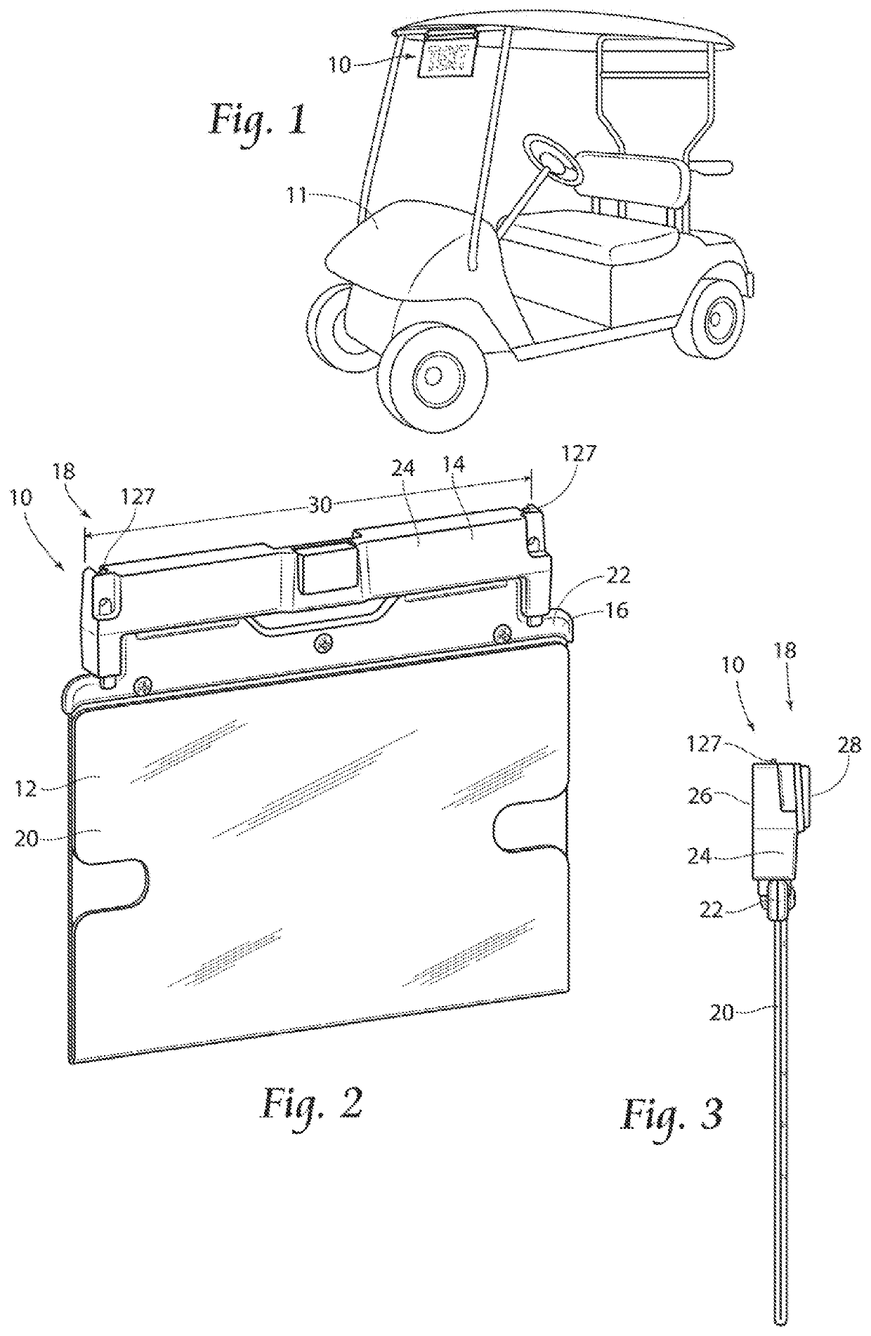
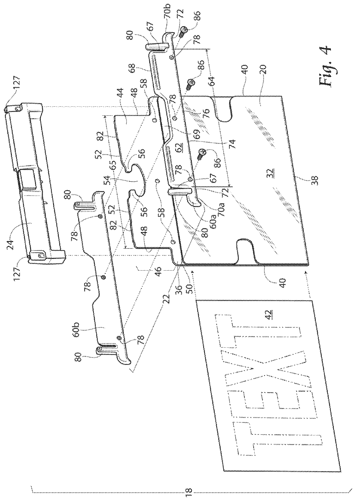
[0008]The present invention relates to an improved device for removably holding a disposable card, such as an information card or score card, and methods of operation of the assembly. The present invention is directed to a novel card holding assembly having a card retaining sleeve, a holder and a collar. The assembly may be temporarily but securely affixed to a supporting structure, such as, by non-limiting example, a golf cart. A first embodiment of the card holding assembly comprises a first embodiment of the card retaining sleeve, a first embodiment of the collar, and a first embodiment of the holder. Wherein the card retaining sleeve, the collar and the holder are in fixed and removable communication. The fixed communication provides for reduced vibration of the card holding assembly while the vehicle on which the card holding assembly is attached is in operation. The card retaining sleeve preferably includes a sleeve body and a top portion. The top portion extends laterally from the sleeve body to form a preferred top marginal edge profile. The profile is adapted for engagement with the collar. The profile is adapted for further engagement in the holder. A top marginal edge portion includes a cut out edge portion which extends inwardly relative to the side marginal edges. The cut out edge portion is further shaped with tabs for engagement with the sleeve holder. The tabs provide for further stability of the assembly when in operation with a vehicle. A top marginal edge ridge extends laterally from the top portion, specifically the top marginal edge portion. The top marginal edge ridge contacts a holder cavity top of the holder, when the sleeve and collar are combined and inserted in the holder, to provide for stability and reduced movement of the card holding assembly. A plurality of thru holes 58 extend thru the top portion, preferably three thru holes, along at least substantially the holder length.
[0009]The collar comprising two collar halves. The collar halves removably connect to the sleeve. At least one collar support post extending laterally from the collar provides for removable communication with the holder. Wherein communication of the collar post and the holder provides for further stability of the assembly.
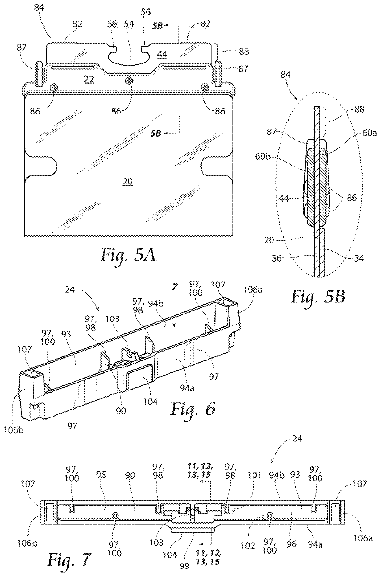
[0010]The holder comprising a cavity for receipt of the profile of the sleeve. The holder preferably comprising at least one ridge within the cavity. Wherein the at least one ridge provides for frictional communication with the sleeve, providing further stability of the assembly.

Problems solved by technology

However, the prior art has had to address continued vibration of the assembly while the vehicle on which the assembly is mounted is in operation.

Method used


Image

  • Display card holder assembly and methods
  • Display card holder assembly and methods
  • Display card holder assembly and methods

Examples


second embodiment

[0077]The profile 46′ is adapted for engagement with the collar 22′. Specifically, the collar 22′ comprising a single piece unit 135 adapted to fit about the profile 46′. Preferably, the collar 22′ is a single piece over-mold unit 136, wherein the collar 22′ is in molded communication with the profile 46′. As illustrated in FIGS. 19A and 19B, the combination the sleeve 20′ and the collar 22′ comprises the sleeve / collar combination 84′.

[0078]As further illustrated in FIGS. 18 and 23, the holder 24″ comprising a lever mechanism 115. The lever mechanism 115 is preferably positioned on the holder operational side 28. The lever mechanism 115 is further preferably positioned in at least in close proximity to a card holding assembly central axis 139. It may be seen that the lever mechanism 115 includes at least two lever mounts 137 oppositely opposed on the operational side 28 and extending opposite the mounting side 26. The lever mechanism 115 further includes a lever 140, a compression s...

third embodiment

[0086]As illustrated in FIGS. 21 and 23, the second side wall 94b″ comprises a groove 118′ extending from at least substantially close to the first holder end 106A′ to at least substantially close to the second holder end 106B′. The groove 118′ defined by a first groove wall 117′ and a groove wall extension 122′. The groove wall extension 122′ in fixed communication with the first groove wall 117′ and extending opposite the lever mechanism 115. The groove 118′ having a groove opening 121′ at least in close proximity to the holder top 92′. The groove extension wall 122′ having at least one groove wall thru hole 119′ in alignment with an at least one first groove wall receiving bore 123′. Wherein at least one of a screw, rivet, and pin 86 may be in removable communication with the at least one groove wall thru hole 119′ and the at least one first groove wall receiving bore 123′. The groove opening 121′ designed to receive a flange 124 extending from a vehicle surface 125 of the vehicl...


PUM


Abstract

A device according to the present invention provides for an improved display card holder assembly and methods of operation. Wherein the improved assembly provides for a sleeve, collar and holder in removable communication to increase stability and reduce vibration of the card holder assembly. The assembly providing for a first embodiment comprising a holder comprising a button mechanism and nodes, and a sleeve comprising tabs and extensions, for increased stability. The assembly providing for a second embodiment comprising a holder comprising a lever mechanism, and at least one of an over-mold and assembled sleeve / collar combination, for increased stability. The assembly providing for a third embodiment comprising a holder comprising a hinge mechanism for increased stability. The invention further providing for methods of operation of the embodiments.

Description

RELATED APPLICATIONS[0001]This application claims the benefit of Provisional Application Ser. No. 62 / 853,866 filed 7 Aug. 2019.BACKGROUND OF THE INVENTION[0002]The present invention relates to an improved device for removably holding a disposable card, such as an information card or score card, and methods of operation of the assembly. Cards such as those contemplated for use with the present invention are commonly used in numerous settings, such as during sporting events during which it is desirable to enable a user to easily mark the card, while also enabling handy storage thereof. For example in the game of golf, carts may be readily identified by information cards attached thereto. Cards may also be used by players to record individual scores along with those of playing companions. In golf, cards such as these also include information about the course being played, such as layout, distances and par. Cards such as these should be readily accessible and removable, for verbiage alt...

Claims


Application Information

Patent Timeline
Patent Type & Authority Patents(United States)
IPC IPC(8): G09F7/18G09F7/10G09F21/04
CPCG09F7/18G09F7/10G09F21/04G09F2007/1865
Inventor PASTERNAK, M. RANDALLSCHAEFER, MARK DONALD
Owner RANDALL MARKETING INT INC
Why Eureka
Try Eureka