Receiving device

a technology of receiving device and antenna module, which is applied in the direction of antenna details, radiating element housings, antennas, etc., can solve the problem that the rfid of each object cannot be accurately read by the antenna module inside the receiving device, and achieve the effect of improving the rfid of each obj

Active Publication Date: 2022-01-04
WISTRON NEWEB
View PDF9 Cites 0 Cited by
  • Summary
  • Abstract
  • Description
  • Claims
  • Application Information

AI Technical Summary

Benefits of technology

[0020]In the embodiments of the invention, each receiving space has one reading antenna module disposed therein, and the reading antenna module read the RFIDs of the objects. The identification rate of the RFIDs of the objects can be improved.

Problems solved by technology

Since the objects are closely arranged, the reading antenna module inside the receiving device cannot accurately read the RFID of each object.

Method used


Image

  • Receiving device
  • Receiving device
  • Receiving device

Examples


first embodiment

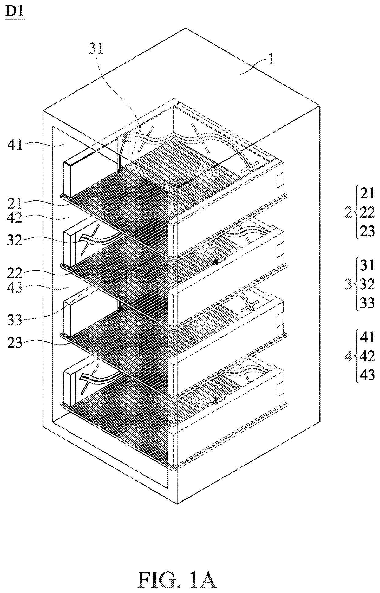
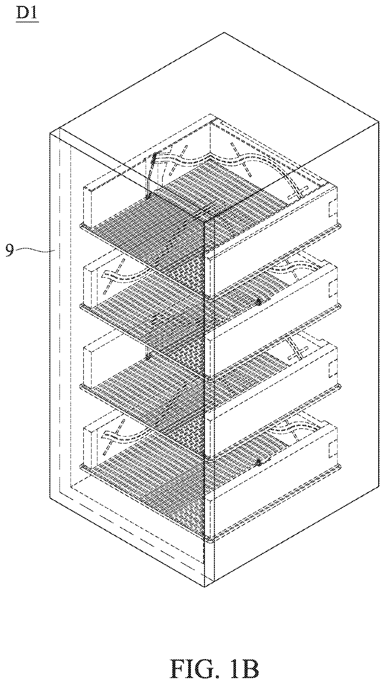
[0033]FIG. 1A is a perspective view of a receiving device D1 of the invention. The receiving device D1 is adapted to receive a plurality of objects (not shown), wherein each object comprises an RFID (not shown). The receiving device D1 includes a device housing 1, a plurality of spacing shelves 2 and a plurality of reading antenna modules 3. The spacing shelves 2 are disposed in the device housing 1, wherein the spacing shelves 2 define a plurality of receiving spaces 4 in the device housing 1. At least some of the receiving spaces 4 overlap each other. The reading antenna modules 3 are respectively disposed in the receiving spaces 4, and are adapted to read the RFIDs of the objects.

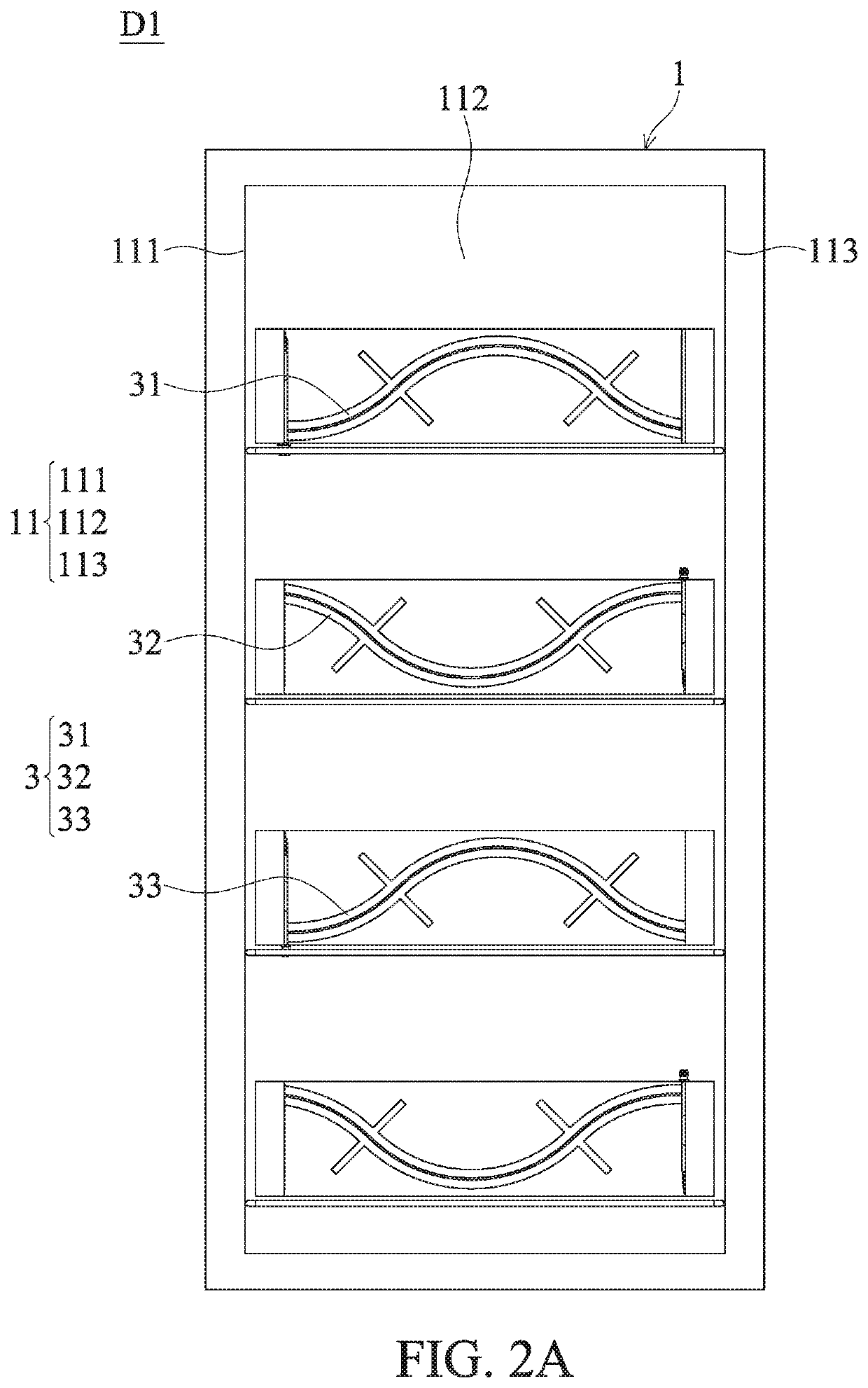
[0034]FIG. 2A is a front view of the receiving device D1 of the first embodiment of the invention. FIG. 2B shows the details of the receiving device D1 of the first embodiment of the invention. With reference to FIGS. 2A and 2B, in one embodiment, the device housing 1 comprises an inner wall 11 and an op...

second embodiment

[0050]FIG. 6A shows a receiving device D2 of the invention. With reference to FIG. 6A, in this embodiment, the first reading antenna module 31′ is only disposed in the first receiving space 41. The first reading antenna module 31′ is only disposed on the first wall 111. The spacing shelves 2 comprise a second shelf 22. The receiving spaces 4 comprise a second receiving space 42. The first shelf 21 and the second shelf 22 define the second receiving space 42. The reading antenna modules 3′ comprise a second reading antenna module 32′. The second reading antenna module 32′ is only located in the second receiving space 42. The second reading antenna module 32′ is only disposed on the second wall 112.

[0051]With reference to FIG. 6A, in this embodiment, the spacing shelves 2 comprise a third shelf 23. The receiving spaces 4 comprise a third receiving space 43. The second shelf 22 and the third shelf 23 define the third receiving space 43. The reading antenna modules 3′ comprise a third r...

third embodiment

[0054]FIG. 6B shows a receiving device D3 of the invention. With reference to FIG. 6B, in this embodiment, the first reading antenna module 31″ is disposed on the first wall 111 and the second wall 112. In this embodiment, the first reading antenna module 31″ is only disposed in the first receiving space 41. The first reading antenna module 31″ is only disposed on the first wall 111 and the second wall 112. The spacing shelves 2 comprise a second shelf 22. The receiving spaces 4 comprise a second receiving space 42. The first shelf 21 and the second shelf 22 define the second receiving space 42. The reading antenna modules 3″ comprise a second reading antenna module 32″. The second reading antenna module 32″ is only located in the second receiving space 42. The second reading antenna module 32″ is only disposed on the second wall 112 and the third wall 113.

[0055]In the receiving device D3 of the third embodiment of the invention, the first reading antenna module 31″ can read the RFI...


PUM


Abstract

A receiving device is provided. The receiving device is adapted to receive a plurality of objects, wherein each object includes an RFID. The receiving device includes a device housing, a plurality of spacing shelves and a plurality of reading antenna modules. The spacing shelves are disposed in the device housing, wherein the spacing shelves define a plurality of receiving spaces in the device housing, and at least some of the receiving spaces overlap each other. The reading antenna modules are respectively disposed in the receiving spaces, and are adapted to read the RFIDs of the objects. The device housing includes an inner wall and an opening. The inner wall includes a first wall, a second wall and a third wall. The first wall faces the third wall. The second wall faces the opening. The reading antenna modules are disposed on the inner wall.

Description

CROSS REFERENCE TO RELATED APPLICATIONS[0001]This Application claims priority of Taiwan Patent Application No. 108116874, filed on May 16, 2019, the entirety of which is incorporated by reference herein.BACKGROUND OF THE INVENTIONField of the Invention[0002]The present invention relates to a receiving device, and in particular to a receiving device with reading antenna modules.Description of the Related Art[0003]Radio frequency identification (RFID) technology is widely used in warehouse management. Conventionally, there are a plurality of spacing shelves disposed in a receiving device. A plurality of objects are disposed on the spacing shelves. Each object includes an RFID. Since the objects are closely arranged, the reading antenna module inside the receiving device cannot accurately read the RFID of each object.BRIEF SUMMARY OF THE INVENTION[0004]In one embodiment, a receiving device is provided. The receiving device is adapted to receive a plurality of objects, wherein each obje...

Claims


Application Information

Patent Timeline
Patent Type & Authority Patents(United States)
IPC IPC(8): H01Q1/22H01Q1/24H01Q1/42
CPCH01Q1/243H01Q1/2216H01Q1/42H01Q13/206
Inventor CHANG, YUAN-LIKUO, CHUN-CHIA
Owner WISTRON NEWEB
Why Eureka
Try Eureka