
Hygienic filter and disposal device

a technology of hygienic filter and disposal device, which is applied in the direction of solid separation, sieving, screening, etc., can solve the problems of litter to develop an odor, litter to become expensive, owner to rake, etc., and achieve the effect of easy filtering out waste and cleanly dumping was

Active Publication Date: 2022-01-18
HERNANDEZ BARRERA JOHN FERNANDO
View PDF32 Cites 0 Cited by
  • Summary
  • Abstract
  • Description
  • Claims
  • Application Information

AI Technical Summary

Benefits of technology

The invention is a mechanical apparatus for cleaning cat litter boxes. It allows for easy and quick filter out of waste, replacement of litter, and clean discard of waste. Components of the apparatus include a main compartment for cat litter, a base platform with a front and back end, and a hinge-based door that allows litter to pass through during lifting and closing of the apparatus. The technical effects of the invention include efficient and effective cleaning of cat litter, reduced waste and odor, and simple and easy use.

Problems solved by technology

The physical shoveling of the waste may be obnoxious and off-putting, while the discarding of a box-full of litter will become expensive, as the litter must be constantly replaced when it could be reused.
A further disadvantage of currently designed litter boxes is that the owner must rake through the litter to find the waste that must be discarded.
This may cause the owner to inadvertently allow waste to sit within the litter for long periods of time, causing the litter to develop an odor and the cat to stop using the litter box.
During this transfer process, waste or unclean litter may fall outside the litter box requiring the owner to further clean the surrounding areas of the litter box.

Method used


Image

  • Hygienic filter and disposal device
  • Hygienic filter and disposal device
  • Hygienic filter and disposal device

Examples


Embodiment Construction

[0025]While the present invention will be described more fully hereinafter with reference to the accompanying drawings, in which one or more embodiments of the present invention is shown, it is to be understood at the outset of the description which follows that persons of skill in the appropriate arts may modify the invention herein described while still achieving the favorable results of this invention. Accordingly, the description which follows is to be understood as being a broad, teaching disclosure directed to persons of skill in the appropriate arts, and not as limiting upon the present invention.

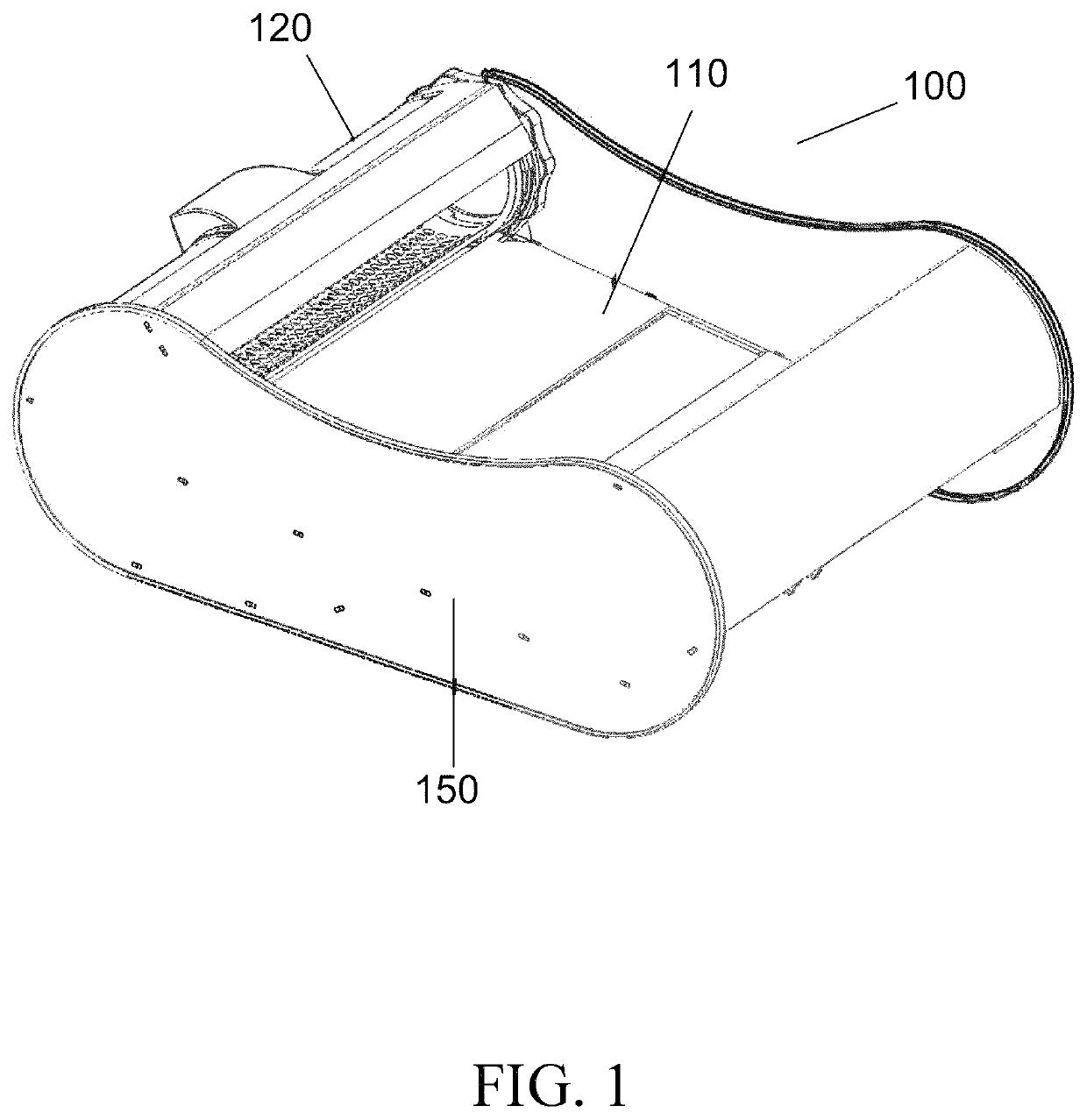
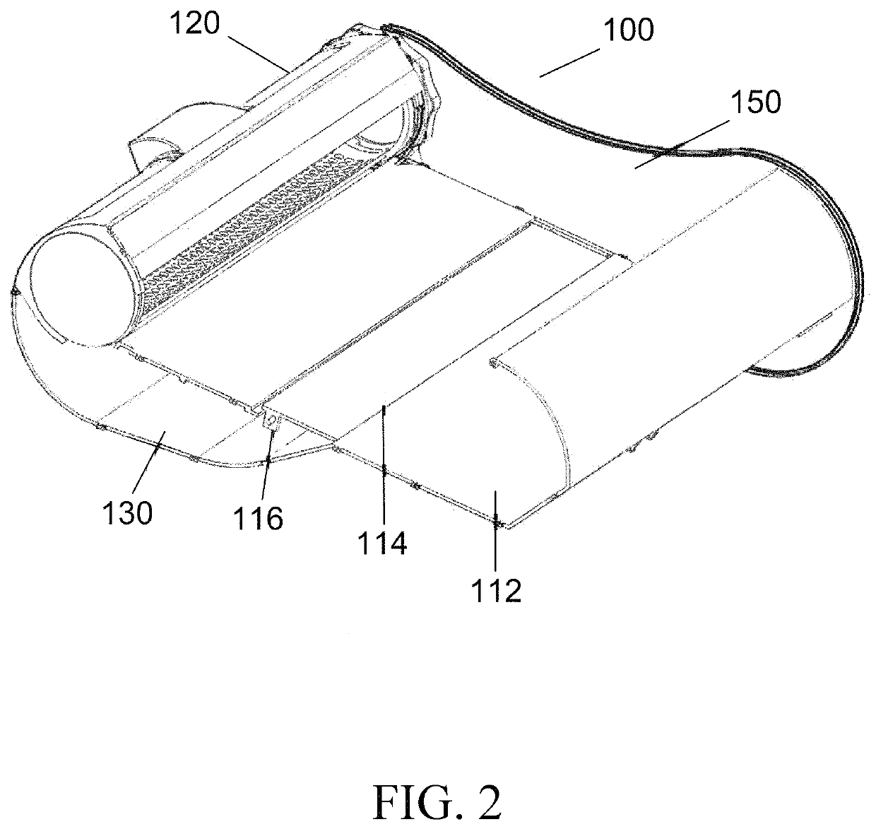
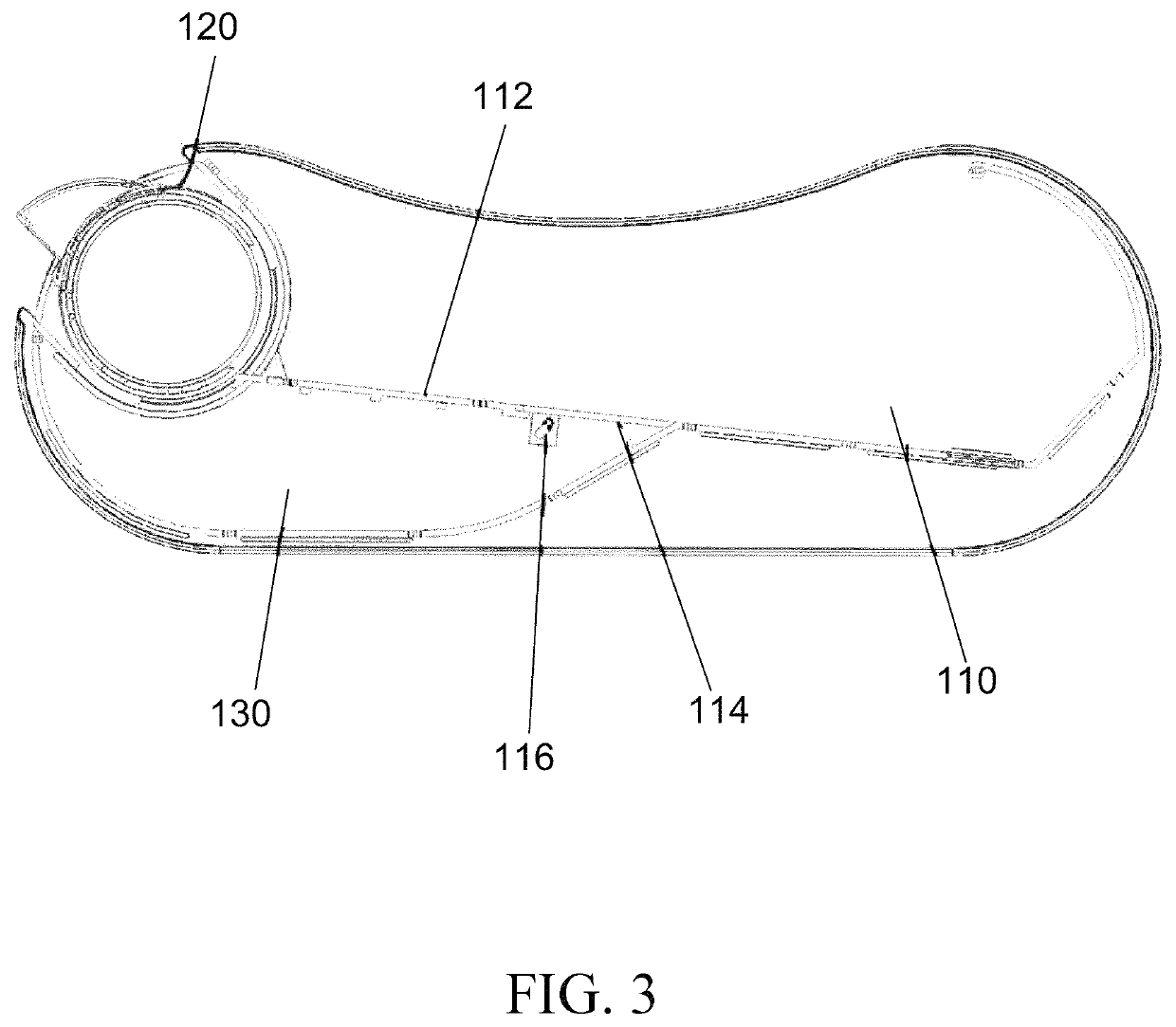
[0026]Referring initially to FIG. 1 and FIG. 2, a first embodiment of a filtration apparatus 100 is shown. The apparatus 100 includes a main compartment 110, a filter element 120 and a secondary compartment 130. The apparatus may further comprise side panels 150. The main compartment 110 comprises a base platform 112 having a front end and a back end. The base platform comprises a do...


PUM


Abstract

A hygienic filter and disposal apparatus comprising a main compartment a base platform, a front end, and a back end, and adapted to contain granular material and waste; a secondary compartment adapted to contain granular material; a door connecting the main compartment to the secondary compartment; and a filter element, comprising porous walls around a cavity and a first opening into said cavity, the walls adapted to filter waste out of the granular material; wherein the back end is proximate to the first opening at a first position where the front end and the back end of the base platform are level; wherein in a second position the front end is lifted higher than the back end and the granular material and waste are directed through the first opening into the cavity; wherein in the second position the filter element retains waste in the cavity and permits the granular material to fall through the porous walls into the secondary compartment; wherein in a third position the back end is higher than the front end and the door opens and directs the granular material into the main compartment; and wherein the device is adapted to sequence from the first position to the second position to the third position.

Description

CLAIM OF PRIORITY[0001]This application is being filed as a U.S. non-provisional patent application under 35 U.S.C. § 111(a) and 37 CFR § 1.53(b). This application claims priority under 35 U.S.C. 119(e) to U.S. provisional patent application Ser. No. 62 / 713,320 filed on Aug. 1, 2018, the contents of which are incorporated herein by reference.FIELD OF INVENTION[0002]The invention relates generally to a filtering waste from cat litter and in particular to a device and method for straining cat litter through a filter and bagging filtered material.BACKGROUND OF THE INVENTION[0003]Cats are among the most popular domesticated pets and often reside within the home of their owners. With regard to feces, a cat's instinct is to dig, deposit the feces, and then cover it. Although originally intended as a means for avoiding being stalked by other predators, the instincts of cats are still present in today's domesticated cats, although their environment has changed. Thus, cat litter boxes are of...

Claims


Application Information

Patent Timeline
Patent Type & Authority Patents(United States)
IPC IPC(8): A01K1/01B07B1/22
CPCA01K1/0114A01K1/011B07B1/22B07B1/18
Inventor HERNANDEZ BARRERA, JOHN FERNANDO
Owner HERNANDEZ BARRERA JOHN FERNANDO
Learn More