Voice transmission apparatus

a transmission apparatus and voice technology, applied in the field of voice transmission apparatus, can solve the problems of downstream congestion or strain on the processing capability of the receiver, the quality of communication may temporarily decline, and the transmission packet is discarded

Inactive Publication Date: 2011-12-20
KYOCERA CORP
View PDF28 Cites 1 Cited by
  • Summary
  • Abstract
  • Description
  • Claims
  • Application Information

AI Technical Summary

Benefits of technology

[0033]According to the present invention, wasteful discarding of transmitted packets is eliminated, a server is no longer subjected to spike loads, and the period of time in which packets to be replayed fail to arrive due to underflow is prevented from being extended.

Problems solved by technology

With a wireless communication channel, communication quality may temporarily decline and, as a result, communication may be lost for a relatively long period of time.
That is, when a large number of packets awaiting transmission are transmitted after a relatively long communication breakdown, in some cases, the transmission causes downstream congestion or strains the processing capability of the receiver.

Method used


Image

  • Voice transmission apparatus
  • Voice transmission apparatus
  • Voice transmission apparatus

Examples


first embodiment

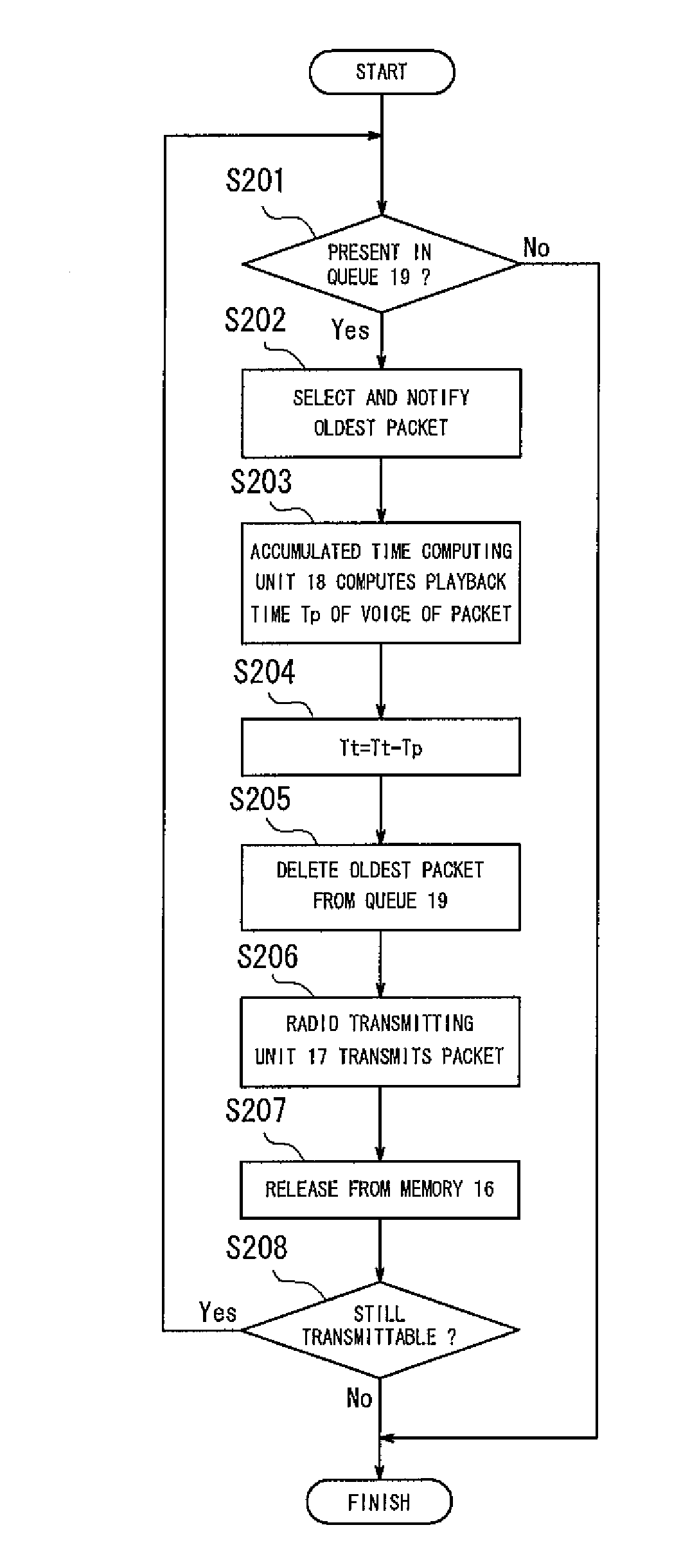
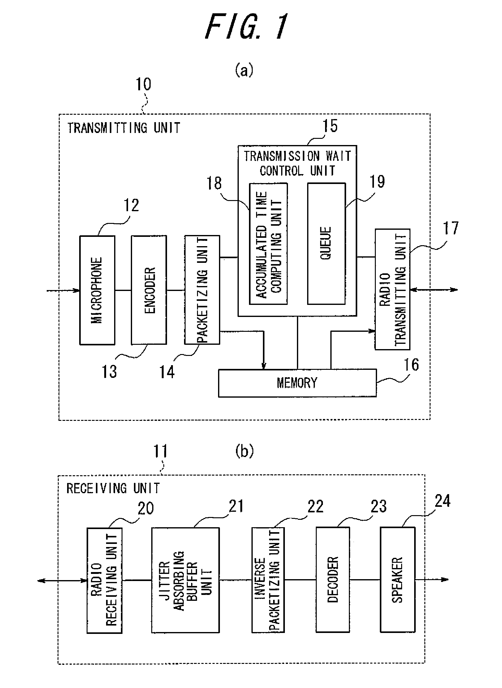
[0074]FIG. 1 shows a transmitting unit and a receiving unit of a voice transmission apparatus according to a first embodiment of the present invention, wherein (a) is a block diagram of the transmitting unit and (b) is a block diagram of the receiving unit. As shown in FIG. 1, a transmitting unit 10 and a receiving unit 11 constitute a voice transmission apparatus incorporated into an integrated terminal apparatus and which communicates with a base station realizing wireless data communication. The transmitting unit 10 includes: a microphone 12; an encoder 13; a packetizing unit 14; a transmission wait control unit 15; a memory 16; and a radio transmitting unit 17. The transmission wait control unit 15 has an accumulated time computing unit 18 and a queue 19. The receiving unit 11 includes: a radio receiving unit 20; a jitter absorbing buffer unit 21; an inverse packetizing unit 22; a decoder 23; and a speaker 24.

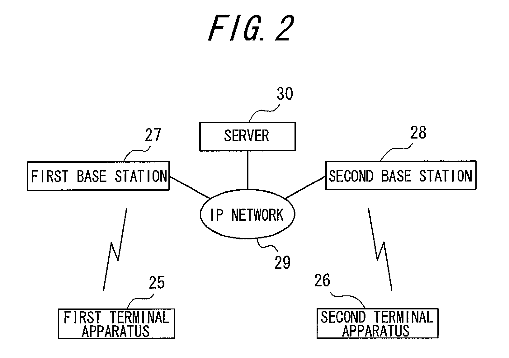
[0075]FIG. 2 is a block diagram illustrating a communication system ba...

second embodiment

[0134]FIG. 7 is a block diagram showing a transmitting unit of a voice transmission apparatus according to a second embodiment of the present invention. As shown in FIG. 7, in place of the transmission wait control unit 15, a transmitting unit 35 includes a transmission wait control unit 36 provided with a function for judging packet discarding. In addition to the accumulated time computing unit 18 and the queue 19, the transmission wait control unit 36 includes a discard judging unit 37. The discard judging unit 37 is provided with a counter 38 and an array 39. Other configurations and effects are similar to those of the transmitting unit 10 (refer to FIG. 1).

[0135]One feature of a voice code is that even if voice frames are randomly lost, by extrapolating from a previous or subsequent frame, the subjective assessment value thereof does not decline significantly. The present embodiment utilizes this feature to discard voice frames with the transmission wait control unit 36 and caus...


PUM


Abstract

A voice transmission apparatus includes a jitter absorbing buffer unit provided in the receiving unit and which absorbs a transmission delay in the packets, and a transmission wait control unit provided in a transmitting unit and which links a packet to be transmitted when transmission temporarily breaks down to a queue. A transmission wait control unit 15 includes an accumulated time computing unit 18 that computes the accumulated time of voice data in packets linked to a queue 19. The transmission wait control unit 15 extracts an oldest linked packet from the queue 19 and discards the same so that the accumulated time computed by the accumulated time computing unit 18 becomes equal to or less than a threshold in order to continuously link a new packet to the queue 19, thereby equalizing the threshold to an accumulation time of a jitter absorbing buffer unit 21.

Description

TECHNICAL FIELD[0001]The present invention relates to a voice transmission apparatus that encodes and communicates voice, and in particular, a voice transmission apparatus improved so as to reduce breakdown periods when communicating via a communication channel that may temporarily break down, such as a wireless LAN (Local Area Network) or a mobile phone network.BACKGROUND ART[0002]Conventionally, apparatuses and methods for transmitting encoded voice via a packet-switching network are known, including, for example, a “Packet-Switching Scheme” (refer to Patent Document 1) and a “Packet Communication Method” (refer to Patent Document 2).[0003]Communication apparatuses to be used in a packet-switching network include those compliant with ATM (Asynchronous Transfer Mode) and IEEE802.3. The recent popularization of high-speed Internet access via cable television, ADSL (Asymmetric Digital Subscriber Line), optical fiber, and the like has led to the practical realization of VoIP (Voice ov...

Claims


Application Information

Patent Timeline
Patent Type & Authority Patents(United States)
IPC IPC(8): H04W4/00H04M11/00H04L47/2416H04L49/9023
CPCH04L29/06027H04L47/10H04L47/2416H04L47/283H04L47/32H04L47/56H04L65/604H04L65/80H04L65/764H04L65/1101
Inventor ENDOH, TAKASHI
Owner KYOCERA CORP
Why Eureka
Try Eureka