Vehicle control device, vehicle control method, and storage medium

a vehicle control and vehicle control technology, applied in vehicle position/course/altitude control, process and machine control, instruments, etc., can solve the problem of not being able to appropriately determine the transition from control based on a lane marking to control in another mod

Active Publication Date: 2022-03-08
HONDA MOTOR CO LTD
View PDF37 Cites 0 Cited by
  • Summary
  • Abstract
  • Description
  • Claims
  • Application Information

AI Technical Summary

Benefits of technology

[0010](3) In the aspect of (1), the traveling control unit may change the predetermined standard such that it becomes easier to continue the first traveling control and it becomes harder to transition to the second traveling control as the vehicle speed of the host vehicle increases.
[0020]According to the above-described (1) to (12), it is possible to appropriately perform determination for performing transition from control based on a lane marking to control in another mode.
[0021]According to (7), it is possible to properly use control based on automatic driving and control based on a lane marking.

Problems solved by technology

However, in the related art, in a case where it is difficult to continuously recognize a lane marking due to reasons such as fading of the lane markings, the weather, and shielding between a camera and a lane marking by surrounding vehicles, it may not be possible to appropriately determine a transition from control based on a lane marking to control in another mode.

Method used


Image

  • Vehicle control device, vehicle control method, and storage medium
  • Vehicle control device, vehicle control method, and storage medium
  • Vehicle control device, vehicle control method, and storage medium

Examples


first embodiment

[0040][Overall Configuration 1]

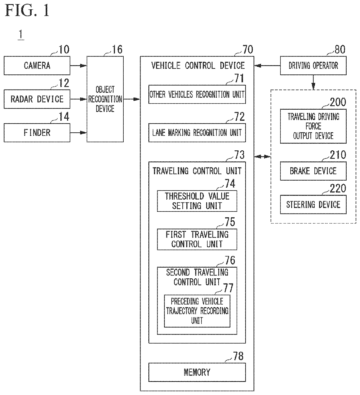
[0041]FIG. 1 is a configuration diagram of a vehicle system 1 using a vehicle control device according to a first embodiment. A vehicle equipped with the vehicle system 1 is a vehicle such as a two-wheeled, three-wheeled, or four-wheeled vehicle, and a driving source thereof is an internal combustion engine such as a diesel engine or a gasoline engine, an electric motor, or a combination thereof. The electric motor operates using power generated by an electric generator connected to an internal combustion engine or power discharged from a secondary battery or a fuel cell.

[0042]The vehicle system 1 includes, for example, a camera 10, a radar device 12, a finder 14, an object recognition device 16, a vehicle control device 70, a driving operator 80, a traveling driving force output device 200, a brake device 210, and a steering device 220. These devices and apparatuses are connected to each other through a multi-communication line such as a controller ar...

second embodiment

[0110]Hereinafter, a vehicle system 1A according to a second embodiment will be described. In the second embodiment, description will be given on the assumption that a traveling control function is realized through automatic driving.

[0111][Overall Configuration 2]

[0112]FIG. 14 is a configuration diagram of the vehicle system 1A according to the second embodiment. The vehicle system 1A includes an automatic driving control device 100 and a vehicle control device 70. The vehicle control device 70 is the same as that described in the first embodiment. The vehicle control device 70 may be omitted from the vehicle system 1A. The automatic driving control device 100 includes a first control unit 120 and a second control unit 150. The automatic driving control device 100 is another example of a “vehicle control device”. The vehicle system 1A further includes a communication device 20, a human machine interface (HMI) 30, a vehicle sensor 40, a navigation device 50, and a map positioning uni...

third embodiment

[0144]Hereinafter, a third embodiment will be described. The third embodiment will be described by adopting the vehicle system 1A of the second embodiment shown in FIGS. 14 and 15 (the second traveling control unit 144 and the preceding vehicle trajectory recording unit 145 are omitted). In the present embodiment, a state where automatic driving by an automatic driving control device 100 is operating is referred to as a “first state”, and a state where the automatic driving control device 100 is stopped is referred to as a “second state”.

[0145]In the third embodiment, in a case of the first state where the automatic driving control device 100 is operating, second traveling control is not performed, and first traveling control (or high-degree traveling control) is executed by a first traveling control unit 143. In a case of the second state where the automatic driving control device 100 is stopped, a vehicle control device 70 executes any one of the first traveling control by a first...


PUM


Abstract

A vehicle control device includes a preceding vehicle recognition unit which recognizes a preceding vehicle, a lane marking recognition unit which recognizes a lane marking for sectioning a lane in which a host vehicle travels, and a traveling control unit which performs first traveling control for causing the host vehicle to travel along a traveling route based on the lane marking recognized by the lane marking recognition unit in a case where the degree of recognition of the lane marking recognized by the lane marking recognition unit satisfies a predetermined standard, and performs second traveling control for causing the host vehicle to travel on the basis of a trajectory of the preceding vehicle recognized by the preceding vehicle recognition unit in a case where the degree of recognition of the lane marking recognized by the lane marking recognition unit does not satisfy the predetermined standard, and the traveling control unit changes the predetermined standard on the basis of a vehicle speed of the host vehicle.

Description

CROSS-REFERENCE TO RELATED APPLICATION[0001]Priority is claimed on Japanese Patent Application No. 2018-180129, filed Sep. 26, 2018, the content of which is incorporated herein by reference.BACKGROUNDField of the Invention[0002]The present invention relates to a vehicle control device, a vehicle control method, and a storage medium.Description of Related Art[0003]In recent years, research has been conducted on a driving support function for supporting the driving and the steering of a vehicle, driving support control for keeping a vehicle in a lane along lane markings (hereinafter, referred to as lane keeping control), driving support control for making a vehicle follow a trajectory of a preceding vehicle (hereinafter, referred to as preceding vehicle following control), driving support control for making a vehicle travel on the basis of a distance between the vehicle and a target present in a horizontal direction (hereinafter, referred to a horizontal direction control), and the li...

Claims


Application Information

Patent Timeline
Patent Type & Authority Patents(United States)
IPC IPC(8): B60W30/18G05D1/02
CPCB60W30/18163G05D1/0214B60W2520/10B60W2554/80B60W2720/24G05D2201/0213B60W30/18B60W10/04B60W10/18B60W10/20G05D1/0248B60W30/12B60W30/165B60W30/182B60W2420/42B60W2555/20B60W2552/53
Inventor KATO, DAICHI
Owner HONDA MOTOR CO LTD
Why Eureka
Try Eureka