Oil containment system and method

a technology oil containment system, which is applied in the direction of sewer system, water installation, construction, etc., can solve the problems of not allowing easy construction of oil containment system, many of the substations of the oil containment system, and the long service life of the pad mounted transformer, so as to achieve the effect of improving and being easy to constru

Pending Publication Date: 2022-11-03
SOLIDIFICATION PRODS INT
View PDF0 Cites 0 Cited by
  • Summary
  • Abstract
  • Description
  • Claims
  • Application Information

AI Technical Summary

Benefits of technology

[0008]It is another object of the present invention to provide an improved and easier process of installing oil containment around a pad mounted transformer.
[0009]A further object of the invention is to provide an oil containment system which may be mounted directly on the transformer pad and may accommodate different configurations to provide total oil containment without having to disturb the outside environment.
[0010]It is yet another object of the present invention to provide an oil containment system which allows for site work on the transformer to be continued easily after installation of the oil containment system.

Problems solved by technology

The majority of electric service transformers contains materials such as transformer mineral oil and / or other natural ester-based fluid which can be harmful to the environment.
This makes utilities subject to oil containment for many of their transformer substations.
One of the largest problems existing to date is incorporating an effective and economic oil containment solution for existing transformers.
The problem is many of these pad mounted transformers have been in service for more than 50 years, long before any regulation existed.
Often these sites do not allow for easy construction of oil containment systems, since no containment was initially required or contemplated at the time of the original installation.
Due to site constraints, significant demolition may be required before a property owner may begin to integrate oil containment systems, including removal of trees, concrete walkways, pavement, etc.
If the containment is below grade or underground, rainwater drainage presents another problem.
Due to these installation concerns, oil containment systems are time-consuming, costly, unsightly during the construction phase, and inefficient.

Method used


Image

  • Oil containment system and method
  • Oil containment system and method
  • Oil containment system and method

Examples


Embodiment Construction

)

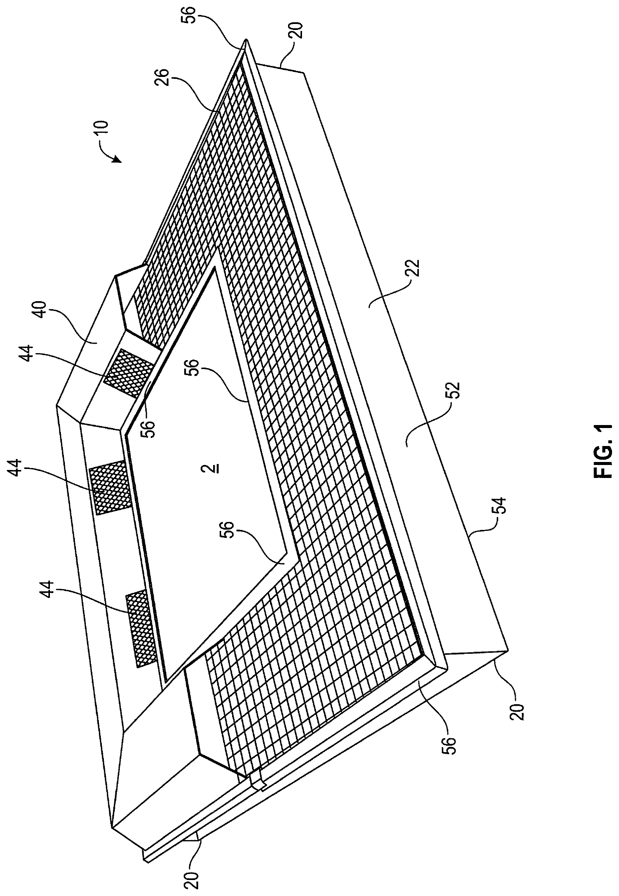
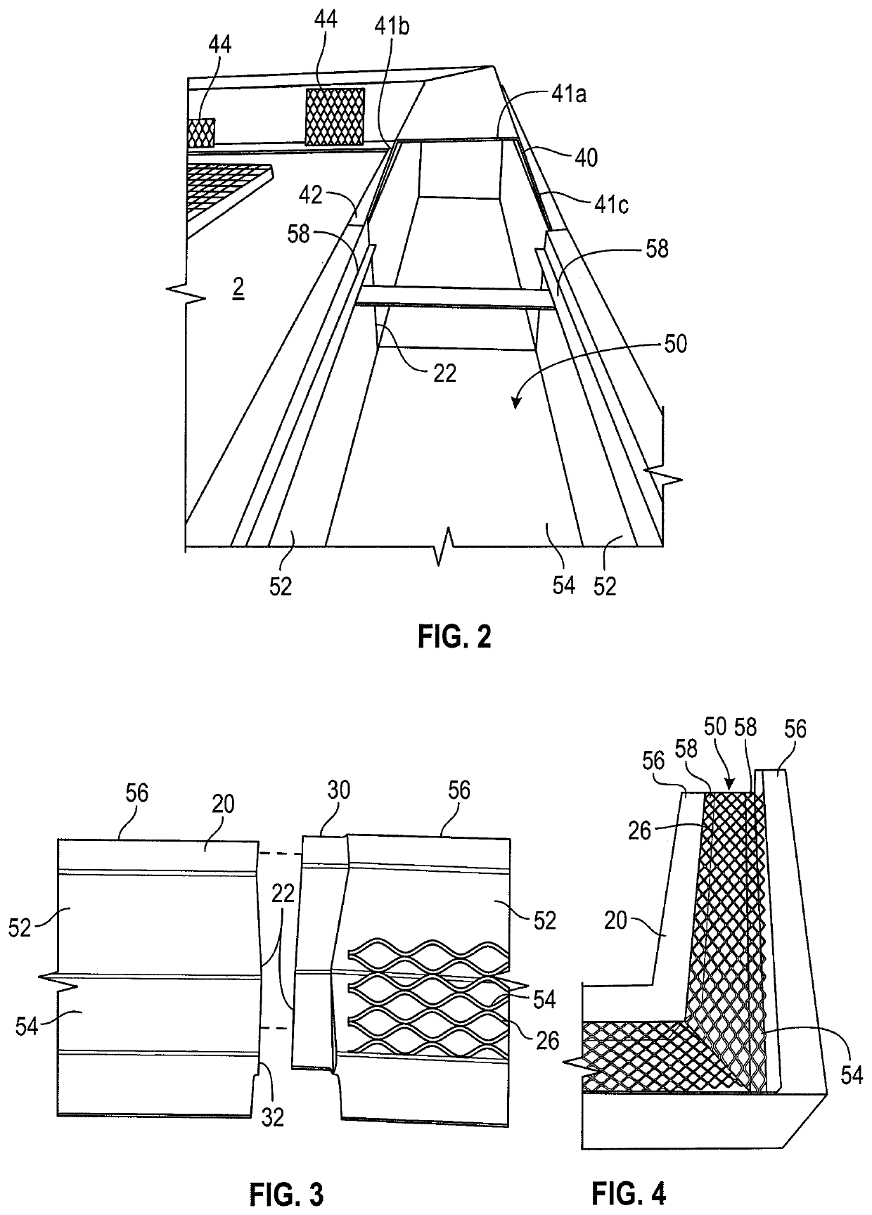
[0050]In describing the embodiment of the present invention, reference will be made herein to FIGS. 1-25 of the drawings in which like numerals refer to like features of the invention.

[0051]As depicted in FIGS. 1 and 2, the oil containment system 10 comprise a series of interlocking containment units 20 which surround a transformer pad 2. While the embodiments of the present invention depicted are incorporated within a pad-mounted transformer, other uses for the oil containment system are not meant to be precluded. The present invention may be utilized within any structure for which containment of transformer mineral oil and other natural ester-based fluids is needed, such as substations, refueling areas, or any other location which include oil tanks and / or other oil-filled equipment. Similarly, while the present invention may be incorporated within a concrete pad, a person of skill in the art would recognize that the present invention should not be so limited. The oil containment ...


PUM


Abstract

An oil containment system and installation method for a transformer mounted on a transformer pad, comprising a plurality of interlocking open-topped containment units. Each of the containment units having a base, a sump formed with two vertically-aligned sidewalls, a first end, and a second end. The sidewalls have support struts extending across the sump and a grate member. At least one of the ends includes a connecting member or a receiving member, the connecting member sized to be placed within the receiving member sized to interlock adjacent containment units. A discriminative outlet is disposed within an opening in the sidewall and includes a filtration media for adsorbing oil from a fluid and subsequently blocking oil flow through the discriminative outlet. The interlocking containment units are secured to the transformer pad around a peripheral edge to restrict the migration of oil to an outside portion of said oil containment system.

Description

BACKGROUND OF THE INVENTION1. Field of the Invention[0001]The present invention relates to structures for the containment of natural ester-based fluids, including transformer mineral oil, from transformers, oil tanks, and other oil-filled equipment.2. Description of Related Art[0002]The majority of electric service transformers contains materials such as transformer mineral oil and / or other natural ester-based fluid which can be harmful to the environment. Depending on its size, a single transformer may carry quantities of these materials as little as 15 gallons, or in excess of 20,000 gallons. Due to the danger of contaminating the environment, countries around the world are enacting legislation and regulation to prevent such an occurrence. In the United States, the Environmental Protection Agency (“EPA”) enacted regulation known as the Spill Prevention, Control, and Countermeasure (“SPCC”), requiring oil filled equipment to have a spill prevention plan in place requiring property ...

Claims


Application Information

Patent Timeline
Patent Type & Authority Applications(United States)
IPC IPC(8): E03F5/04E03F5/16
CPCE03F5/0404E03F5/16F16N31/00
Inventor GANNON, WILLIAM J.MELACCIO, PAULPERROTTI, CHESTER
Owner SOLIDIFICATION PRODS INT
Why Eureka
Try Eureka