Vehicle seat

a technology for vehicles and seats, applied in the field of vehicles, can solve the problem that the related art cannot be expected to be effective in improving the blood circulation of the seated occupants

Active Publication Date: 2022-06-07
NHK SPRING CO LTD
View PDF12 Cites 0 Cited by
  • Summary
  • Abstract
  • Description
  • Claims
  • Application Information

AI Technical Summary

Benefits of technology

[0005]In consideration of the above circumstances, an object of the present disclosure is to obtain a vehicle seat capable of suppressing swelling of the legs of a seated occupant.
[0007]According to the above configuration, the seat cushion supports the buttocks and thighs of the seated occupant. The temperature changing section provided to the seat cushion is capable of switching between the first state in which the temperature changing section operates so as to warm the seated occupant from the front end portion of the seat cushion, and the second state in which the temperature changing section does not operate so as to warm the seated occupant from the front end portion of the seat cushion. The control section controls the temperature changing section so as to alternate repeatedly between the first state and the second state in a state in which an occupant is sitting on the seat cushion. Accordingly, at least a region corresponding to the back of the knees of the seated occupant and the vicinity thereof, namely a region comparatively distant from the heart and close to veins (in other words a region where veins are close to the skin) is warmed intermittently, thus effectively improving the blood circulation of the seated occupant.
[0009]According to the above configuration, the air blower mechanism serving as the temperature changing section supplies warm air toward at least the seat front upper side through the front end portion of the seat cushion when in the first state, and supplies cool air toward at least the seat front upper side through the front end portion of the seat cushion when in the second state. At least a region corresponding to the back of the knees of the seated occupant and the vicinity thereof is thus warmed and cooled, thereby even more effectively improving the blood circulation of the seated occupant.
[0011]According to the above configuration, the physical build information acquisition section acquires the information relating to the physical build of the occupant sitting on the seat cushion. The control section controls the air blower mechanism based on the information acquired by the physical build information acquisition section so as to increase the rate at which air is supplied by the air blower mechanism the larger the physical build of the seated occupant. Accordingly, at least a region corresponding to the back of the knees of the seated occupant and the vicinity to the lower side thereof can be effectively warmed and cooled even in a case the seated occupant has a large physical build and there is therefore a greater distance from the front end portion of the seat cushion to the back of the knees of the seated occupant and the vicinity to the lower side thereof.
[0013]According to the above configuration, the planar heater serving as the temperature changing section is disposed in the front end portion of the seat cushion and is powered to generate heat when in the first state and placed in the unpowered state when in the second state. Accordingly, at least a region corresponding to the back of the knees of the seated occupant and the vicinity thereof is warmed intermittently by a simple configuration, thus effectively improving the blood circulation of the seated occupant.
[0014]As described above, the vehicle seat of the present disclosure exhibits the excellent advantageous effect of enabling swelling of the legs of the seated occupant to be suppressed.

Problems solved by technology

This related art cannot necessarily be expected to be effective in improving the blood circulation of the seated occupant, and leaves room for improvement from the perspective of suppressing swelling of the legs of the seated occupant.

Method used


Image

  • Vehicle seat
  • Vehicle seat
  • Vehicle seat

Examples


first exemplary embodiment

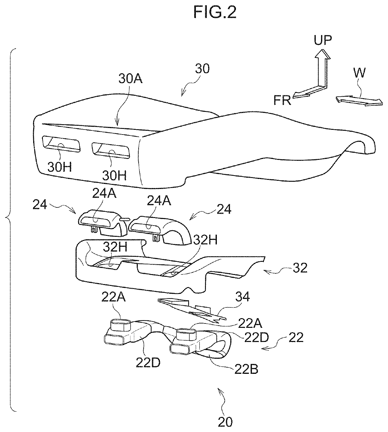
[0025]Explanation follows regarding a vehicle seat according to a first exemplary embodiment of the present disclosure, with reference to FIG. 1 to FIG. 5. In the drawings, the arrow FR indicates a seat front side, the arrow UP indicates a seat upper side, and the arrow W indicates a seat width direction, as appropriate.

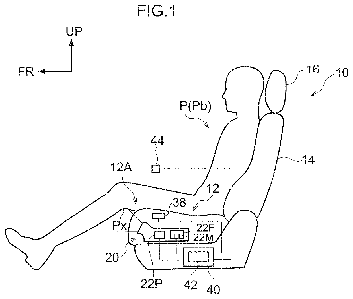
[0026]FIG. 1 is a schematic side view illustrating a vehicle seat 10 according to the present exemplary embodiment. As illustrated in FIG. 1, the vehicle seat 10 includes a seat cushion 12 to support the buttocks and thighs of a seated occupant P, a seatback 14 to support the back of the seated occupant P, and a headrest 16 to support the head of the seated occupant P. The seat cushion 12 is configured by covering a seat cushion frame (not illustrated in the drawings) with a cushion pad 30 (see FIG. 2), and covering a surface of the cushion pad 30 with an outer cover. An air blower mechanism 20 (illustrated schematically in the drawings) is provided inside the seat c...

second exemplary embodiment

[0048]Next, explanation follows regarding a vehicle seat 50 according to a second exemplary embodiment of the present disclosure, with reference to FIG. 6 to FIG. 9. FIG. 6 is a schematic side view illustrating the vehicle seat 50 according to the present exemplary embodiment. FIG. 7 is a perspective view illustrating a lower section of the vehicle seat 50. As illustrated in FIG. 6 and FIG. 7, the vehicle seat 50 differs from the vehicle seat 10 according to the first exemplary embodiment (see FIG. 1) in the respect that a planar heater 52 is provided as a temperature changing section instead of the air blower mechanism 20 (see FIG. 1). Configurations other than those described below are effectively equivalent to those of the first exemplary embodiment. Those configuration sections that are effectively equivalent to those of the first exemplary embodiment are accordingly allocated the same reference numerals, and explanation thereof is omitted.

[0049]As illustrated in FIG. 6 and FIG....


PUM


Abstract

A vehicle seat including: a seat cushion configured to support buttocks and thighs of a seated occupant; a temperature changing section that is provided at the seat cushion and is switchable between a first state in which the temperature changing section operates so as to warm the seated occupant from a front end portion of the seat cushion, and a second state in which the temperature changing section does not operate so as to warm the seated occupant from the front end portion of the seat cushion and a control section configured to control the temperature changing section so as to alternate repeatedly between the first state and the second state in a state in which an occupant is sitting on the seat cushion.

Description

CROSS-REFERENCE TO RELATED APPLICATION[0001]This application is based on and claims priority under 35 USC 119 from Japanese Patent Application No. 2019-204262 filed on Nov. 11, 2019, the disclosure of which is incorporated by reference herein.BACKGROUNDTechnical Field[0002]The present disclosure relates to a vehicle seat.Related Art[0003]Technology is known that attempts to relieve fatigue in a seated occupant by warming and cooling the seated occupant at a seat up-down direction intermediate portion of a seatback and at a seat front-rear direction intermediate portion of a seat cushion (see, for example, Japanese Patent Application Laid-Open (JP-A) No. 2018-193057).[0004]However, in this related art, regions of the seated occupant that are warmed and cooled are within regions supported by the seat, and correspond to locations comparatively close to the heart and distant from any veins (in other words locations where veins are found far below the skin). This related art cannot neces...

Claims


Application Information

Patent Timeline
Patent Type & Authority Patents(United States)
IPC IPC(8): B60N2/56B60H1/00
CPCB60N2/5657B60H1/00285B60N2/5635B60N2/5678B60H2001/003B60N2/5685B60N2/002
Inventor KIM, DONGHYOUNIMANARI, KATSUTOSHI
Owner NHK SPRING CO LTD
Why Eureka
Try Eureka