Battery module and battery pack

a battery module and battery pack technology, applied in the field of batteries and battery modules, can solve the problems of increasing the amount of battery swelling, increasing the capacity of the battery, and causing the outer jacket (=case) to swell, so as to achieve the effect of suppressing the swelling of batteries in the battery modul

Active Publication Date: 2021-01-07
PANASONIC INTELLECTUAL PROPERTY MANAGEMENT CO LTD
View PDF0 Cites 0 Cited by
  • Summary
  • Abstract
  • Description
  • Claims
  • Application Information

AI Technical Summary

Benefits of technology

[0010]According to the present invention, the swellin...

Problems solved by technology

In addition, electrode bodies themselves swell, thereby causing the outer jacket (=case) to swell.
Particularly in recent years, the capacity of the battery has been increased, and an amount of swelling of the battery tends to increase.
However, if the binding bar is made thicker, it is diff...

Method used


Image

  • Battery module and battery pack
  • Battery module and battery pack
  • Battery module and battery pack

Examples


modified example

[0049]FIG. 5(A) is a plan view showing a schematic structure of a first restraining member according to a modified example. FIG. 5(B) is a front view showing a schematic structure of the first restraining member according to the modified example. FIG. 5(C) is a plan view showing a schematic structure of a second restraining member according to the modified example. FIG. 5(D) is a front view showing a schematic structure of the second restraining member according to the modified example.

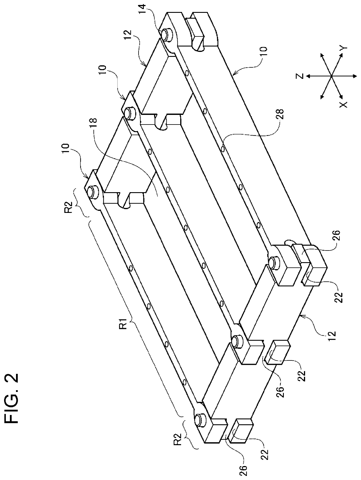
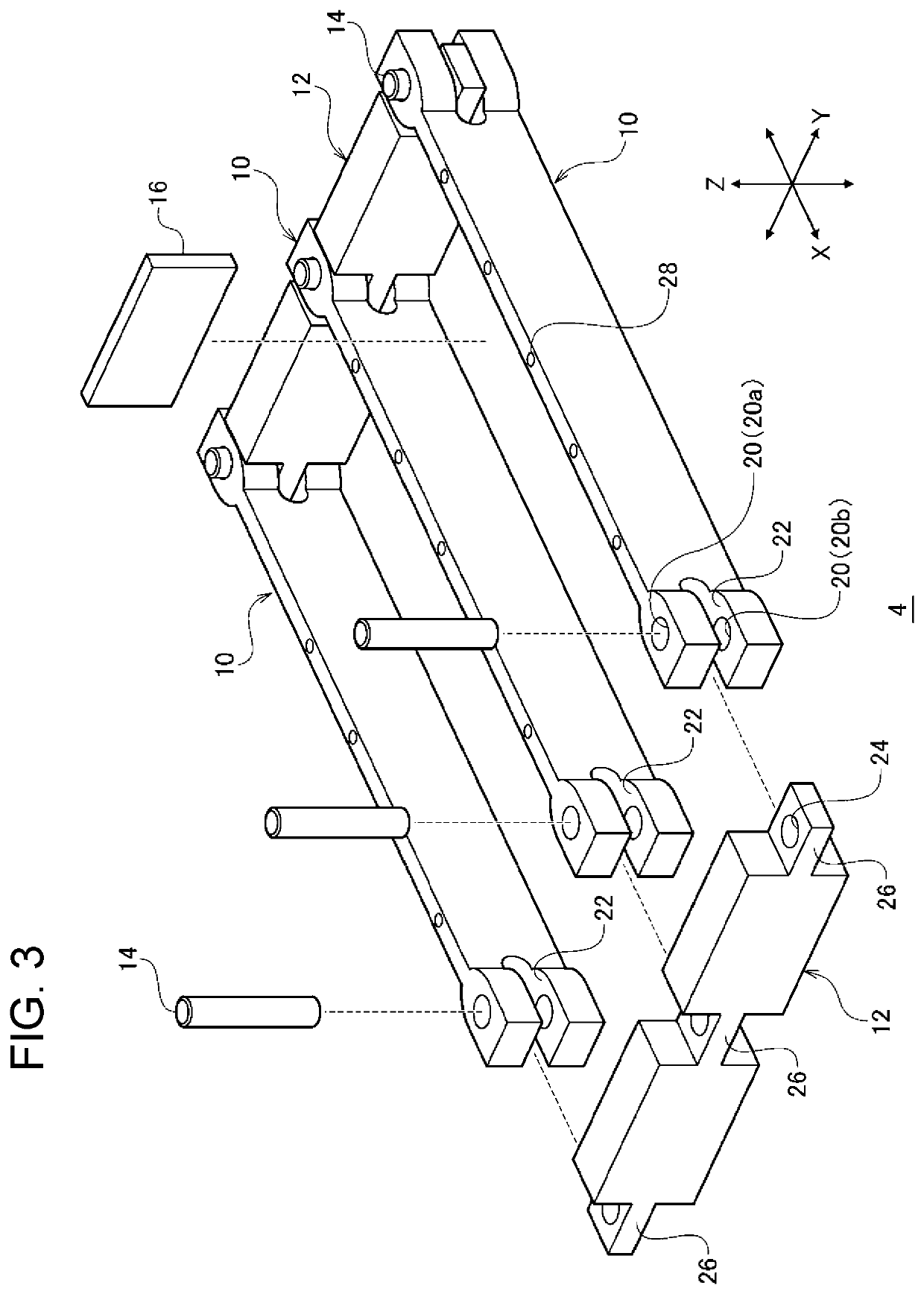
[0050]In the exemplary embodiment, first restraining member 10 has cutouts 22, and second restraining member 12 has narrow-width parts 26. On the other hand, in the modified example, first restraining member 10 has narrow-width parts 26, and second restraining member 12 has cutouts 22. Such a structure as described above can also provide an effect similar to that in the exemplary embodiment. Alternatively, both of first restraining member 10 and second restraining member 12 have cutouts 22, and cutout...


PUM


Abstract

A battery module includes: a battery stack having a plurality of batteries; a plurality of first restraining members and a plurality of second restraining members; and connecting members. The first restraining members and the second restraining members define a housing space for the battery stack. Each of the first restraining members has a first housing part extending in a direction intersecting a planar direction in which the battery stack, the first restraining members, and the second restraining members are arranged, and each of the second restraining members has a second housing part extending in the planar direction. Each of the connecting members connects each of the first restraining members and each of the second restraining members to each other by being housed in the first housing part of each of the first restraining members and in the second housing part of each of the second restraining members.

Description

TECHNICAL FIELD[0001]The present invention relates to a battery module and a battery pack.BACKGROUND ART[0002]As a power source for, for example, a vehicle and the like that require a high output voltage, there is known a battery stack configured with a plurality of series-connected batteries (for example, see PTL 1). In general, a battery stack has a module structure in which a predetermined number of batteries are stacked and are fastened with binding bars. Further, a plurality of the battery stacks are housed in a chassis (=housing) for a battery pack.CITATION LISTPatent Literature[0003]PTL 1: Unexamined Japanese Patent Publication No. 2012-181970SUMMARY OF THE INVENTION[0004]In the conventional battery module, battery stacks are sandwiched by a pair of end plate. Further, both end parts of each binding bar are bent, and their tip ends are fixed to the end plates. With this arrangement, the batteries in a stacking direction of the batteries are fastened.[0005]Regarding the batter...

Claims


Application Information

Patent Timeline
IPC IPC(8): H01M2/10H01M50/209H01M50/264
CPCH01M2/1077Y02E60/10H01M10/052H01M2220/20H01M50/105H01M50/103H01M50/141H01M50/204H01M50/249H01M50/264H01M50/209H01M50/293H01M50/291H01M50/258H01M50/20
Inventor NORIMINE, SHOTATAJIMA, MITSUTOSHIOGINO, HIROTAKA
Owner PANASONIC INTELLECTUAL PROPERTY MANAGEMENT CO LTD
Why Eureka
Try Eureka