Method of detecting state-of-charge of battery and power device

a technology of power devices and batteries, applied in the field of detecting power devices, can solve the problems of inability to uniquely determine the state of charge by this method, difficult to accurately presume the state of charge from only the voltage of batteries, and the error of the detection of the state of charge. to achieve the effect of more accurate detection of the state of charge of batteries

Inactive Publication Date: 2006-04-13
SANYO ELECTRIC CO LTD
View PDF1 Cites 50 Cited by
  • Summary
  • Abstract
  • Description
  • Claims
  • Application Information

AI Technical Summary

Benefits of technology

[0008] The present invention has been made in order to solve these problems. It is a main object of the present invention to provide a m

Problems solved by technology

The reason is that the magnitude and temperature of the discharge current makes an error of the detection of the state-of-charge.
While there is also a method of measuring a voltage of a battery to detect the state-of-charge of the battery, moreover, it is impossible to uniquely determine the state-of-charge by this method.
It is hard to accurately presume the state-of-charge from only the voltage of the battery.
Thus, it is hard to accurately detect the state-of-charge of the battery.
For this reason, it is more difficult

Method used


Image

  • Method of detecting state-of-charge of battery and power device
  • Method of detecting state-of-charge of battery and power device

Examples


Embodiment Construction

(Power Device 100)

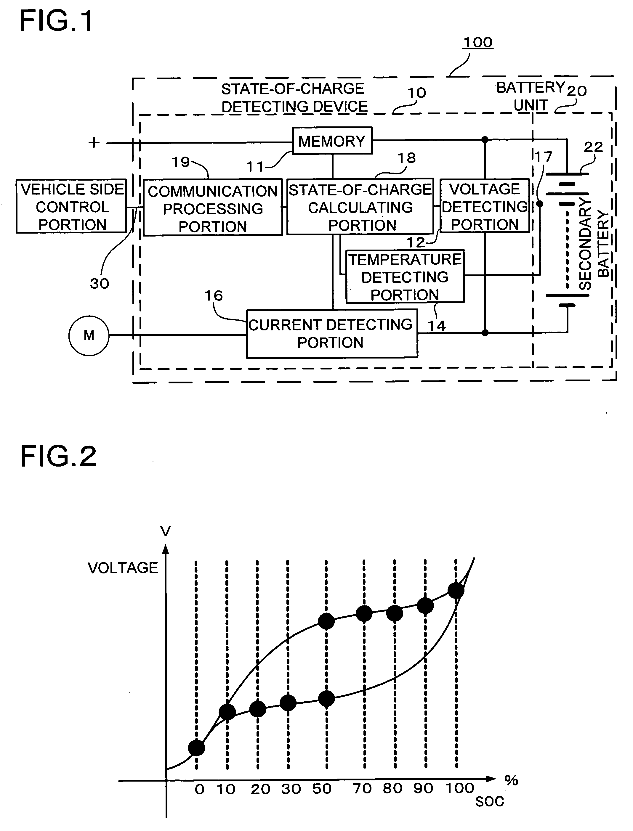
[0025]FIG. 1 is a block diagram showing a structure of a power device according to an embodiment of the present invention. A power device 100 shown in FIG. 1 comprises a battery unit 20 including a secondary battery 22 and a state-of-charge detecting device 10. The state-of-charge detecting device 10 includes a voltage detecting portion 12 for detecting a voltage of a battery, a temperature detecting portion 14 for detecting a temperature of the battery, a current detecting portion 16 for detecting a current flowing to the battery, a state-of-charge calculating portion 18 for calculating signals input from the voltage detecting portion 12, the temperature detecting portion 14 and the current detecting portion 16 to detect a state-of-charge of the battery and detecting a maximum limit current value of the battery unit 20 from the state-of-charge and the temperature of the battery, and a communication processing portion 19 for transmitting, to connecting equipment,...


PUM


Abstract

A method of detecting a state-of-charge of a battery detects a current of a battery and a voltage of the battery, calculating a state-of-charge of the battery as a first state-of-charge based on an integration of the current of the battery thus detected, while calculating the state-of-charge of the battery as a second state-of-charge based on the voltage of the battery and calculating a synthetic state-of-charge obtained by taking a weighted mean of the first state-of-charge and the second state-of-charge as the state-of-charge of the battery, and weighting the weighted mean in order to increase weighting of the second state-of-charge in a region in which a capacity of the battery is increased and a region in which the capacity of the battery is reduced and to increase weighting of the first state-of-charge in other regions.

Description

BACKGROUND OF THE INVENTION [0001] 1. Field of the Invention [0002] The present invention relates to a method of detecting a state-of-charge of a battery and a power device, and more particularly to a state-of-charge detecting method of detecting a state-of-charge of a battery included in a power device for driving a vehicle operating motor and the power device, for example. [0003] 2. Description of the Related Art [0004] The power device can increase the number of power modules having a battery or a simple battery connected in series or in parallel and can thus increase an output current, and can raise an output voltage depending on the number of the batteries connected in series. In a power device to be used for requiring a large output, for example, in a power device to be used for a vehicle such as a car, a bicycle or a tool, particularly, it is possible to employ a structure in which a plurality of batteries is connected in series to increase an output. For example, in a power ...

Claims


Application Information

Patent Timeline
IPC IPC(8): H02J7/00
CPCG01R31/3651G01R31/3624G01R31/3842G01R31/367Y02E60/10H02J7/0048H01M10/486
Inventor TATSUMI, HIROSHIYAMAUCHI, YUTAKAYASUTOMI, FUMIOINUI, SHINYA
Owner SANYO ELECTRIC CO LTD
Why Eureka
Try Eureka