Safety arrangement and medical delivery device

a safety arrangement and medical technology, applied in the field of safety arrangements, can solve the problems of ejecting the proximal portion of the medicament container carrying the injection needle, the elements of the broken medicament container cannot be effectively held at the front of the delivery device, and the syringe, cartridge and similar are prone to breakage,

Active Publication Date: 2022-08-02
SHL MEDICAL AG
View PDF9 Cites 0 Cited by
  • Summary
  • Abstract
  • Description
  • Claims
  • Application Information

AI Technical Summary

Benefits of technology

[0021]The drawbacks affecting the prior art are overcome by providing the safety arrangement with a blocking element and with a corresponding blocking initiating structure. The blocking element is arranged between the shell and the container holder. The blocking initiating structure is arranged to repositioning the blocking element when the container holder moves in the proximal direction relative to the shell, e.g., upon initiation of an injection process which can automatically be triggered by a driving mechanism of a medicament delivery device, to prevent at least a portion of the container from leaving the shell when breaking. By virtue of the blocking element and the blocking initiating structure, the container or at least broken portions thereof and particularly portions with the orifice potentially carrying the needle can be prevented from passing the blocking element. Like this, the container or the mentioned portions can be hindered from leaving the shell such that they can be held inside the system. In that way, particularly potentially harmful parts such as a part carrying the needle or parts contaminated with a substance such as a medicament or pathogens can be kept safe inside the system. Thus, the safety of the medical delivery device into which the safety arrangement is integrated can be increased.
[0047]Preferably, the medicament delivery device comprises a driving mechanism arranged to forward a plunger rod into the body of the container when being activated. Thereby, the driving mechanism can be embodied for manual or semiautomatic and particularly for automatic forwarding or displacing of the plunger rod. Such driving arrangement allows for a particularly convenient delivery or injection of the medicament.

Problems solved by technology

Even when provided with a distal flange, however, medicament containers such as syringes, cartridges and similar remain prone to breakages, for several reasons e.g. during an injection procedure, due to the pressure applied by a plunger rod activated by a driving mechanism of the medicament delivery device; and / or because of tissue resistance during needle penetration and / or in case the medicament delivering devices wherein they are lodged are dropped and / or pre-existing micro cracks in the medicament container as is common.
In case of breakage, especially in consideration of the above introduced rigid needle shield configuration, elements of broken medicament container cannot be effectively held at the front of the delivery device and, due to the force applied by the driving mechanism for displacing the plunger rod, tend to be ejected from the delivery device.
In particular, ejecting the proximal portion of the medicament container carrying the injection needle can be dangerous.
However, the arrangement proposed in U.S. Pat. No. 8,715,246 B2 is affected by a number of drawbacks.
Flexible arms permanently gripping on a syringe shoulder and integrating protrusions which come to rest in a gap between a rigid needle shield and such shoulder bring about the problem of making the removal of the rigid needle shield by an operator more difficult.
In fact, such kind of holder may irregularly increase the resistance to removal of the needle shield and make the operation more unpredictable.
The inevitable, designed-in interference between flexible arms of holders and the rigid needle shield may damage the needle or partially expose it to a different environment, already at a non-injecting stage.
Moreover, a design incorporating thin, elongated flexible arms and ledges is liable to damage and unnecessarily complicates manufacturing and assembling processes.

Method used


Image

  • Safety arrangement and medical delivery device
  • Safety arrangement and medical delivery device
  • Safety arrangement and medical delivery device

Examples


Embodiment Construction

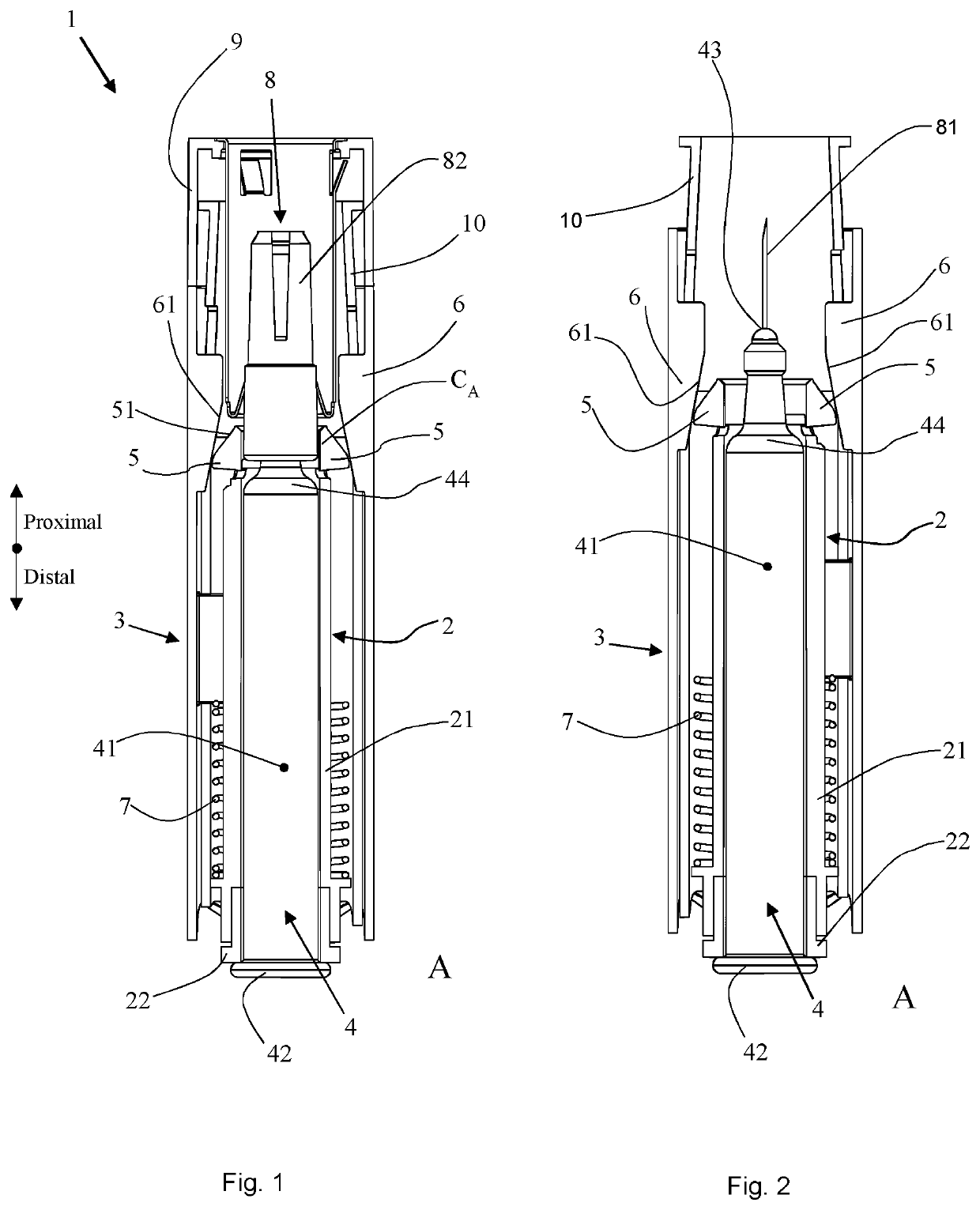
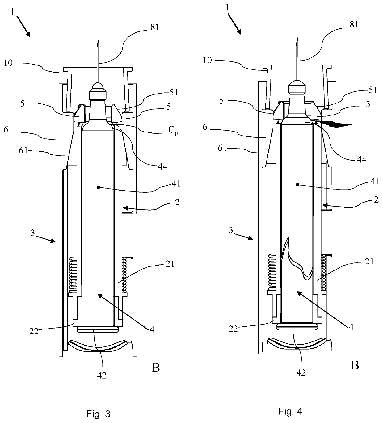
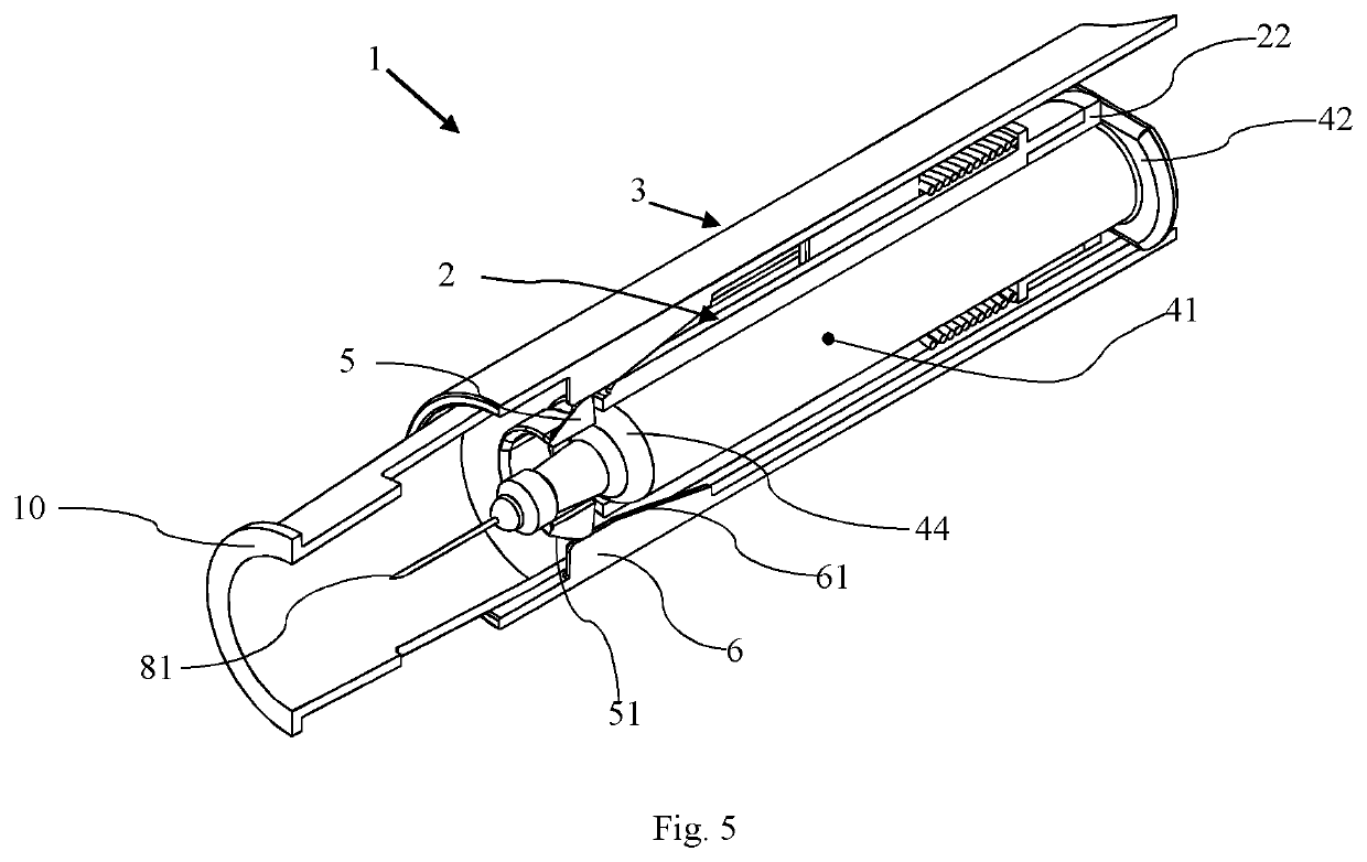
[0057]In the following description, certain terms are used for reasons of convenience and are not intended to limit the invention. The terms “right”, “left”, “up”, “down”, “under” and “above” refer to directions in the figures. The terminology comprises the explicitly mentioned terms as well as their derivations and terms with a similar meaning. Also, spatially relative terms, such as “beneath”, “below”, “lower”, “above”, “upper”, “proximal”, “distal”, and the like, may be used to describe one element's or feature's relationship to another element or feature as illustrated in the figures. These spatially relative terms are intended to encompass different positions and orientations of the devices in use or operation in addition to the position and orientation shown in the figures. For example, if a device in the figures is turned over, elements described as “below” or “beneath” other elements or features would then be “above” or “over” the other elements or features. Thus, the exempl...


PUM


Abstract

A safety arrangement for being used in a medicament delivery device, comprising a container holder with a body section and a flange seat and a shell. The container holder is arranged to receive a container with a longitudinal body at one end passing over into a distal flange and at an opposite end passing over into a proximal orifice via a shoulder, such that the distal flanges of the container contacts the flange seat of the container holder. Moreover, the container holder is arranged in the shell such that the container holder is movable in a proximal direction in relation to the shell. A blocking element is arranged between the shell and the container holder. A blocking initiating structure is arranged to reposition the blocking element when the container holder is moved in the proximal direction in relation to the shell from a first position to a second position.

Description

CROSS REFERENCE TO RELATED APPLICATIONS[0001]The present application is a U.S. National Phase Application pursuant to 35 U.S.C. § 371 of International Application No. PCT / EP2018 / 057854 filed Mar. 28, 2018, which claims priority to European Patent Application No. 17163522.0 filed Mar. 29, 2017. The entire disclosure contents of these applications are hereby incorporated by reference into the present application.TECHNICAL FIELD[0002]The present invention relates to a safety arrangement to be used in a medicament delivery device according to the preamble of independent claim 1 and more particularly to a safety arrangement comprising a container holder arranged to receive a flange-retained syringe, cartridge or similar containers for delivery of a medicament via a needle.[0003]The present invention also relates to a medicament delivery device especially modified to comprise and cooperate with such a safety arrangement.[0004]Such a safety arrangement device can be implemented in medicame...

Claims


Application Information

Patent Timeline
Patent Type & Authority Patents(United States)
IPC IPC(8): A61M5/315A61M5/24A61M5/32
CPCA61M5/31501A61M5/24A61M5/3202A61M2205/02A61M5/2033A61M5/3213A61M2005/206A61M5/3243
Inventor LINIGER, JÜRGMÜRI, MARTINTHÜER, THOMASREILLY, DECLANCAMMISH, NEIL B.OLSON, STEPHAN
Owner SHL MEDICAL AG
Why Eureka
Try Eureka