

Safety Arrangement for Use in a Motor Vehicle
- Summary
- Abstract
- Description
- Claims
- Application Information
AI Technical Summary
Benefits of technology
Problems solved by technology
Method used
Image

Examples
Embodiment Construction
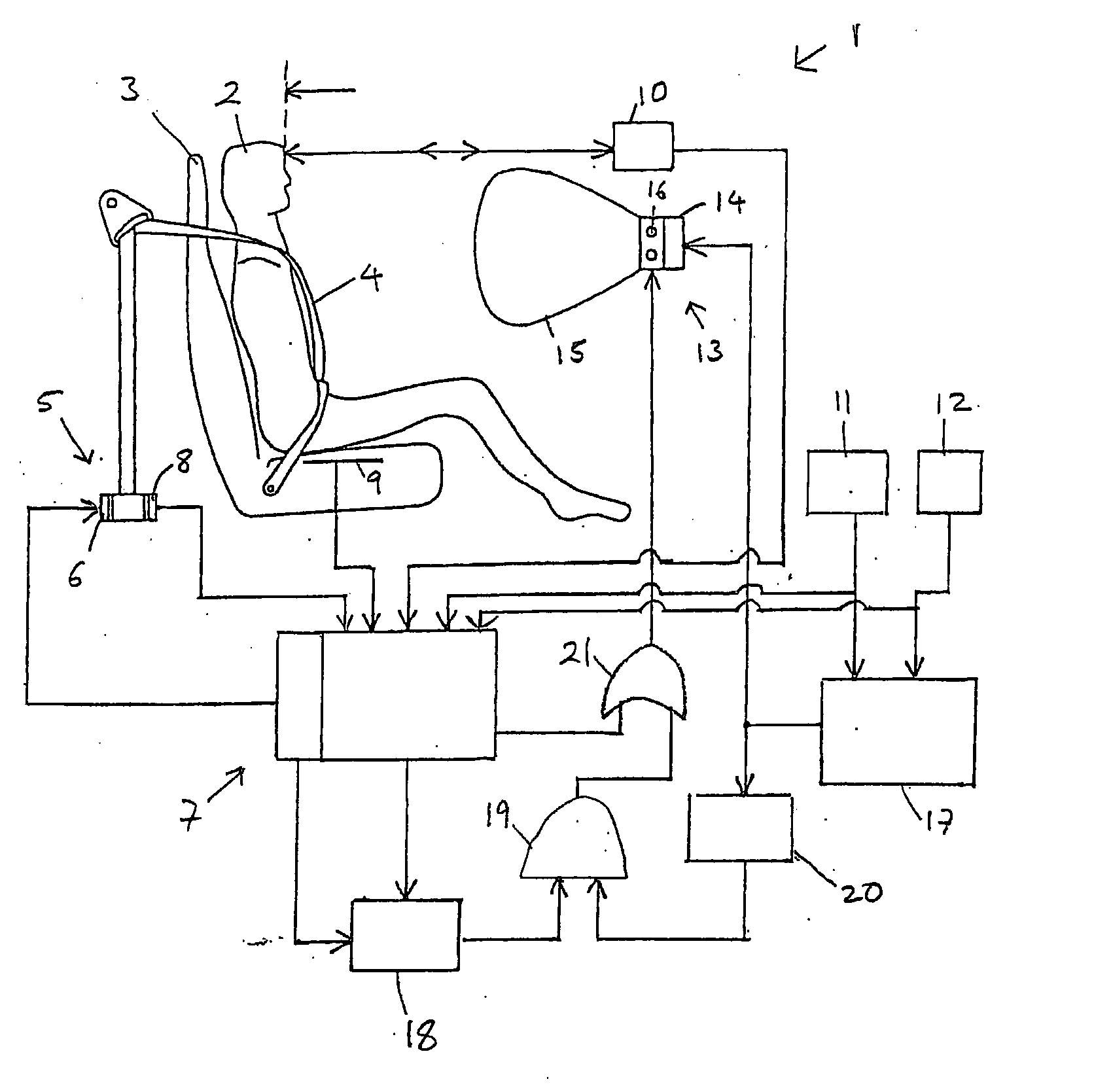
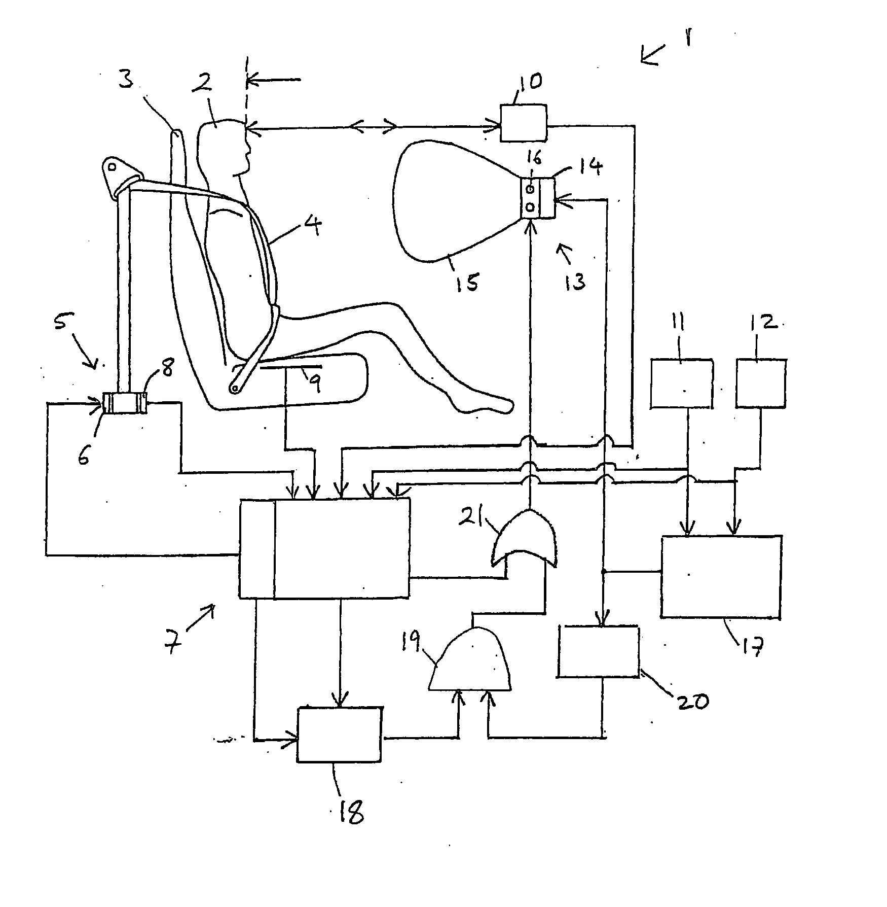
[0020]Referring to FIG. 1, a safety arrangement 1 is installed within a vehicle to protect an occupant 2 in the event that an accident occurs. The vehicle is provided with a seat 3 for the occupant 2. A safety-belt 4 is associated with the seat 3. In this embodiment, the safety-belt 4 is a three-point belt. The arrangement incorporates a retractor 5 which the safety-belt 4 may be wound into or paid-out from. The retractor 5 incorporates an adaptable load-limiter 6, which may be used, in the event that an accident occurs, to provide a selected energy absorbing resistance as the safety-belt 4 is paid-out from the retractor 5 after the retractor 5 has locked during the accident. The adaptable load-limiter 6 is controlled by a signal from a central control unit 7 which sets the energy absorbing resistance to be applied by the load-limiter 6. In a modified embodiment a constant load-limiter could be used.
[0021]The retractor 5 also incorporates an angle measurement device 8, which is used...
PUM
 Abstract
Description
Claims
Application Information