Pipe grabber

a technology of pipe handler and pipe handler, which is applied in the direction of drilling rods, drilling pipes, drilling casings, etc., can solve the problems of inability to safely secure the pipe, mechanical assistance, and the inability of the apparatus to safely hold the pipe, so as to facilitate the selective attachment and removal of the pipe grabber, and avoid any scrubbing motion during activation. , to achieve the effect of safe and reliable holding of the pip

Active Publication Date: 2022-08-02
FORUM US
View PDF3 Cites 0 Cited by
  • Summary
  • Abstract
  • Description
  • Claims
  • Application Information

AI Technical Summary

Benefits of technology

[0024]A first object of the invention is to provide a pipe grabber that will safely and reliably hold a pipe within a pipe handler trough. A second object of the invention is to secure the pipe with even movement of the jaws, so as to avoid any scrubbing motion during activation. Another object of the present invention is to facilitate the selective attachment and removal of the pipe grabber, so that the pipe grabber may be affixed only when required by a particular drilling platform installation. Yet another object of the present invention is to ensure the handling of a pipe will proceed as it would without the pipe grabber being installed, and without any added risk or potential interference between the grabber and either the pipe or other machinery during use when the grabber is inactive. A further object of the invention is to ensure that the attachment, use, and maintenance of the pipe grabber is intuitive.

Problems solved by technology

Consequently, the handling of these large and heavy pipes is not suited to manual labor, and instead requires mechanical assistance.
While illustrating a very functional pipe grabber having a number of benefits, there remain disadvantages that are also associated with these apparatus.
The use of two independent hydraulic cylinders, one to operate each jaw, leads to several deficiencies.
While such cylinders tend to be very reliable, in the event of a partial malfunction of one, the apparatus does not safely secure the pipe, and yet the operator may not be aware of the lack of adequate holding force in the partially malfunctioning cylinder.
Further, the two independent cylinders may not operate synchronously, particularly with wear and build-up of debris over time, meaning one jaw may close ahead of the other.
In such case, the pipe may be “scrubbed” back and forth during the effecting of the gripping, which can either lead to a complete failure to secure the pipe, or alternatively lead to wear or damage of the trough over time even when the pipe is ultimately adequately secured.
This device lacks any mechanism to ensure centering and even pressure is initially applied during the gripping sequence, a deficiency which may not be of consequence when simply holding a pipe during threading and unthreading as described in the patent, but which as noted above will result in undesirable shifting and scrubbing motion when used with a pipe trough.
Another limitation of many of the prior art grabbers is a risk of potential interference between the inactive pipe grabber and other equipment or processes.

Method used


Image

  • Pipe grabber
  • Pipe grabber

Examples


Embodiment Construction

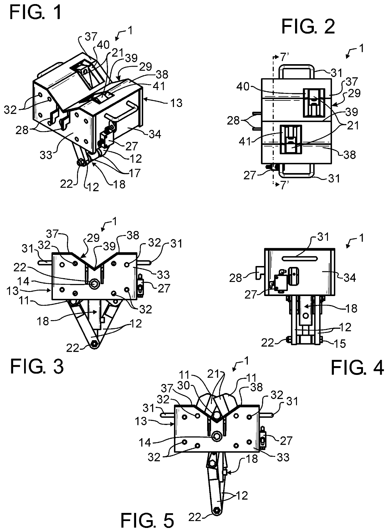
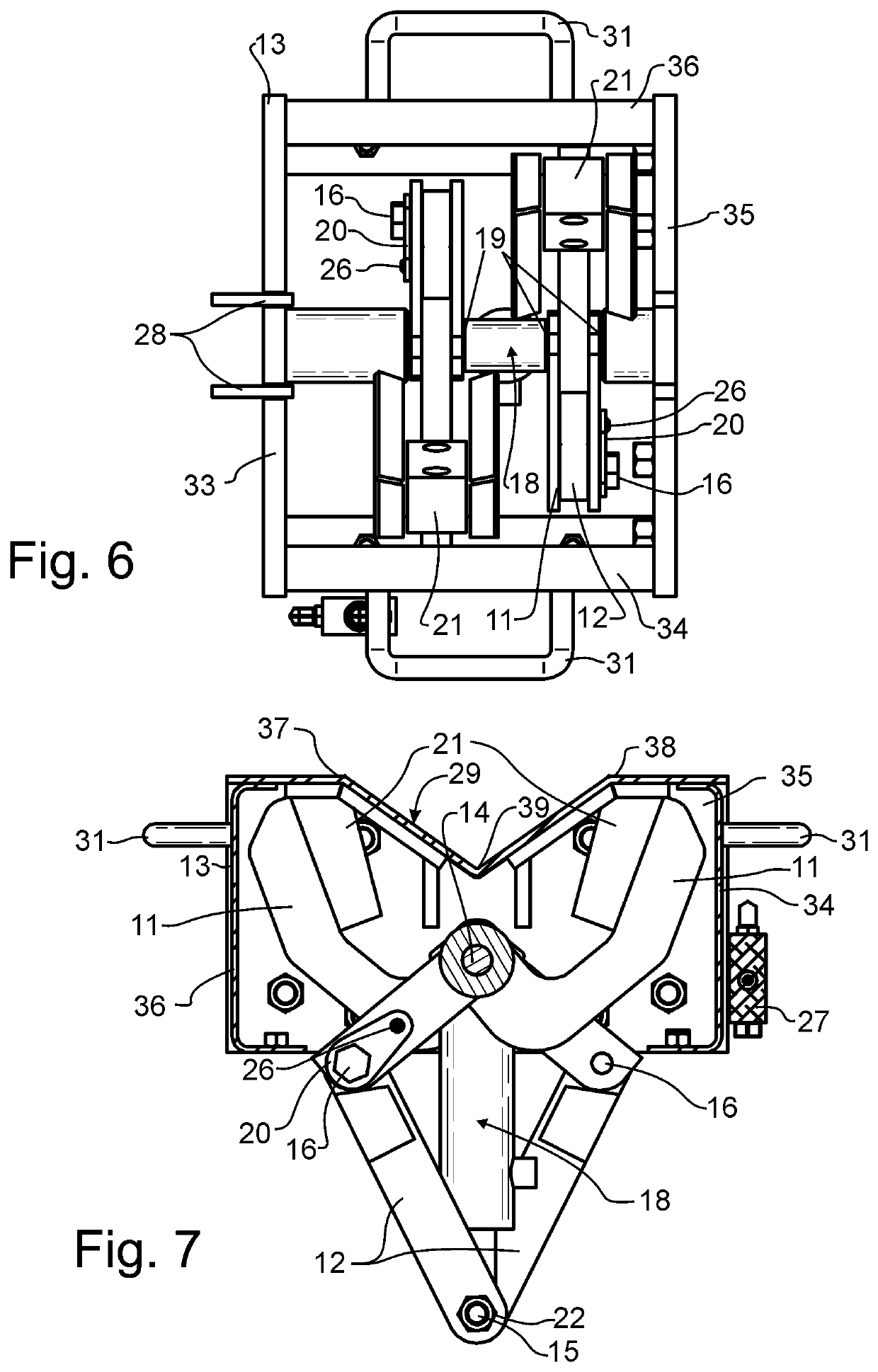
[0030]Manifested in the preferred embodiment, the present invention provides a pipe grabber1 that may be selectively activated to securely hold a pipe within the trough of a pipe handler. In a preferred embodiment of the invention, pipe grabber 1 may be selectively activated to engage a pipe such as pipe 30 illustrated in FIG. 5, or may be fully retracted below the pipe trough such as illustrated in FIGS. 1-4, 6, and 7.

[0031]Preferred embodiment pipe grabber 1 is comprised of a pipe grabber box 13 which defines a housing or container for the remaining components. Preferred embodiment pipe grabber 1 may be lifted by an installer grasping with one hand on each respective handle 31. The installer will then engage a pair of L-shaped support hooks 28 in and hook on to the end of an existing pipe handler such as illustrated in the present applicant's commonly owned U.S. Pat. Nos. 9,388,647 and 9,845,646 incorporated by reference herein above. This temporarily supports preferred embodiment...


PUM


Abstract

A pipe grabber is readily installed onto a pipe handler used to elevate large and heavy sections of pipe to and from a drilling platform. The pipe grabber has a pair of upper link arms pivotal about an upper cylinder pin, a pair of lower link arms pivotal about a lower cylinder pin, a pair of link pins coupling individual ones of the pair of upper link arms to individual ones of the pair of lower link arms, and a hydraulic cylinder affixed between the upper and lower cylinder pins. The pipe grabber captures a pipe within the pipe supporting trough when the cylinder is extended, and the upper link arms are configured to retract within a pipe grabber housing beneath the pipe supporting trough when the cylinder is retracted. A pair of hooks protrude from a housing side wall to suspend the pipe grabber from a pipe handler.

Description

CROSS REFERENCE TO RELATED APPLICATIONS[0001]The present application is a continuation of U.S. patent application Ser. No. 16 / 518,978 filed Jul. 22, 2019 and granted as U.S. Pat. No. 10,920,504 on Feb. 16, 2021, and claims the benefit of U.S. provisional patent application 62 / 701,412 filed Jul. 20, 2018, each of like title and inventorship, the teachings and entire contents which are incorporated herein by reference.BACKGROUND OF THE INVENTION1. Field of the Invention[0002]This invention pertains generally to material or article handling, and more particularly to a pipe handler such as might commonly be used in the oil drilling and rigging industry and in the well servicing industry to assist with the handling of very large and heavy pipes that are regularly raised to and lowered from an elevated drilling platform. More particularly, the present invention pertains to a pipe grabber that is used to securely retain a pipe within the pipe handler when so required or desired.2. Descript...

Claims


Application Information

Patent Timeline
Patent Type & Authority Patents(United States)
IPC IPC(8): E21B19/15
CPCE21B19/155E21B19/15E21B19/06
Inventor JESERITZ, MICHAEL R.COCKERLINE, IAN F.
Owner FORUM US
Why Eureka
Try Eureka