Supercharge Your Innovation With Domain-Expert AI Agents!

Distributed radio signal targeting device

a radio signal and target device technology, applied in the direction of direction finders, measurement devices, instruments, etc., to achieve the effect of light, mobile and inexpensiv

Active Publication Date: 2022-08-02
TRUENORTH RESCUE INC
View PDF4 Cites 0 Cited by
  • Summary
  • Abstract
  • Description
  • Claims
  • Application Information

AI Technical Summary

Benefits of technology

The system provides high accuracy and sensitivity in determining the direction of arrival of signals from rescue beacons, enabling precise location determination with reduced complexity and cost, and is adaptable for use with both 121.5 MHz and 406 MHz frequencies.

Problems solved by technology

This disclosure relates to direction finding systems and more particularly to the utilization of information from a phased array antenna and boom assembly that may provide unparalleled accuracy in its lines of bearing.

Method used


Image

  • Distributed radio signal targeting device
  • Distributed radio signal targeting device
  • Distributed radio signal targeting device

Examples


Embodiment Construction

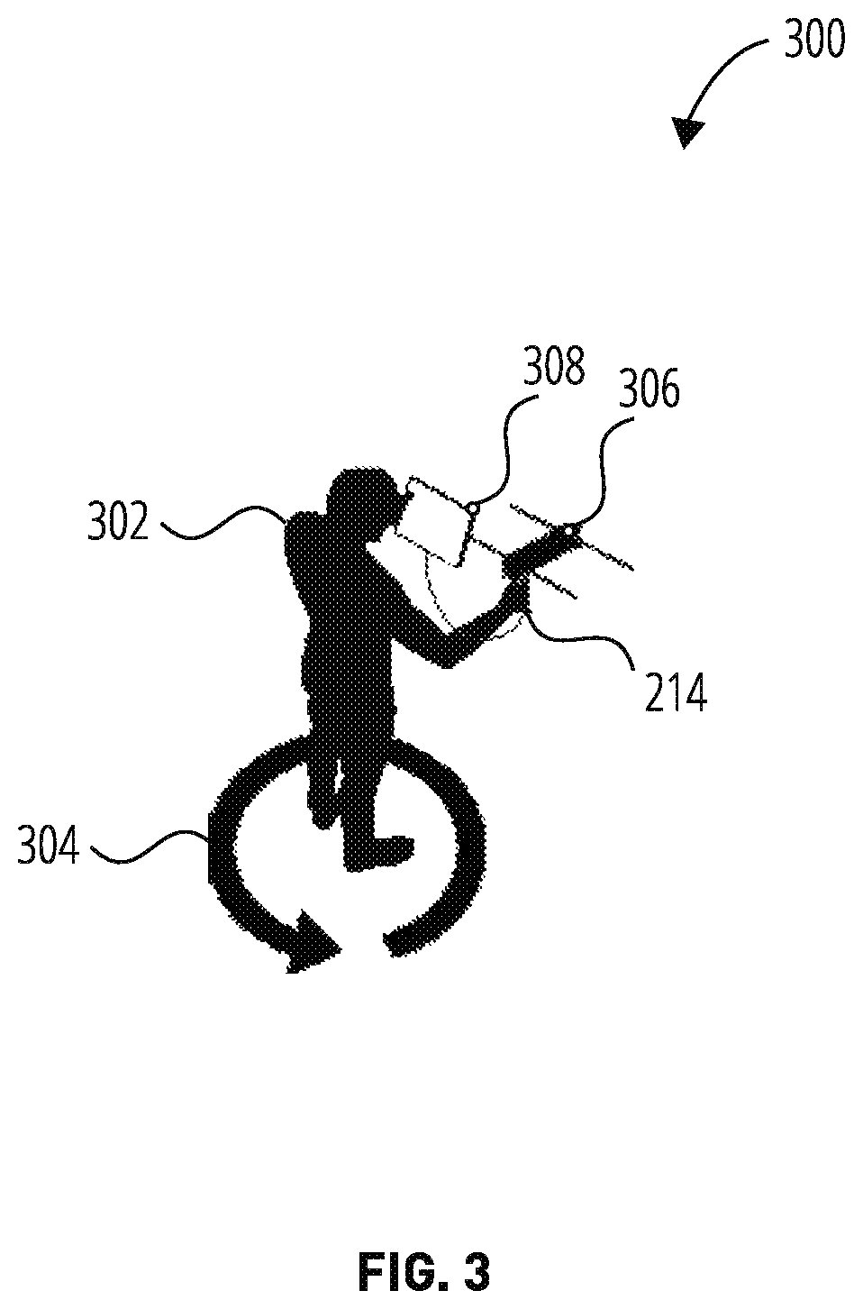
[0021]“Portable direction” refers to a user-directed means of finding a target emitter.

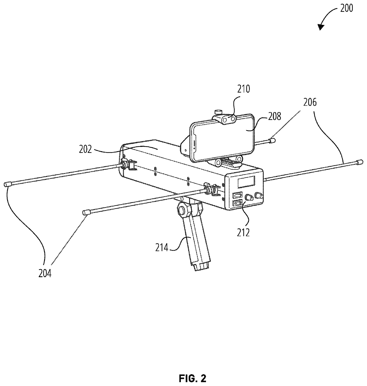
[0022]“Housing” refers to the physical encasement of the portable direction finder.

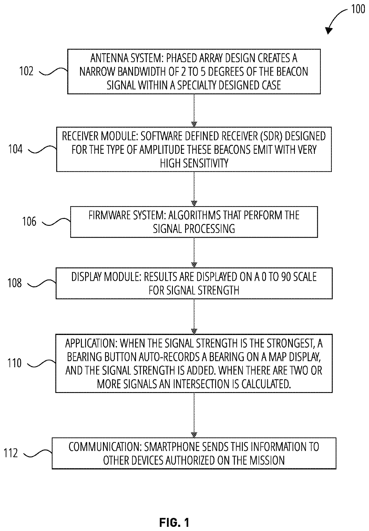
[0023]“Antenna and boom assembly” refers to the portion of a device for receiving an electrical signal from rescue beacons that may be used in direction finding.

[0024]“Phased-array antenna” refers to a set of antennae within the antenna and boom assembly that may include two dipole elements used to receive 121.5 MHz signals.

[0025]“Receiver assembly” refers to a component within the portable direction finder including a radio frequency module and a digital signal processing module.

[0026]“Radio frequency module” refers to a component of the receiver assembly that receives a signal from the antenna and boom assembly (also known as an RF module).

[0027]“Digital signal processing module” refers to a component of the receiver assembly in communication with various components, such as an electronic compass interface, boom c...


PUM


Abstract

Apparatuses and methods are disclosed that allow for the detection, identification and direction finding of search and rescue beacons in a variety of environments. The techniques may be used to identify a line of bearing (LOB) to 121.5 MHz rescue beacons found in aircraft (ELTs), marine beacons (EPIRBs), and personal locator beacons (PLBs). Multiple lines of bearing may be used to geo-locate a target emitter if so desired. The methods may utilize, for example, a handheld device that is designed for search and rescue activity. Additionally, this device may be able to decode a 406 MHz frequency beacon that communicates with the satellite system that is controlled by COSPAS SARSAT. This constellation of rescue satellites coordinates the location of 406 MHz rescue beacons.

Description

BACKGROUND[0001]This disclosure relates to direction finding systems and more particularly to the utilization of information from a phased array antenna and boom assembly.[0002]In numerous applications (e.g., electronic warfare, navigational and related systems), a requirement exists for high accuracy lines of bearings from the direction of arrival of an electrical signal. The signal, for example, may be generated by either one of the 406 MHz or 121.5 MHz rescue beacons.[0003]The conventional method employed for direction finding has been the use of a multi-element Yagi antenna and boom assembly that is directional, but is large and unwieldy in mobile applications. These devices may be mounted on vehicles, airplanes or watercraft.[0004]While various systems have been proposed in the past to resolve the ambiguity indicated above (determining a small, precise area in which to conduct a search) to provide accurate direction-finding readings, these systems normally involve the use of tw...

Claims


Application Information

Patent Timeline
Patent Type & Authority Patents(United States)
IPC IPC(8): G01S5/02G01S19/17G01S3/32
CPCG01S5/0231G01S3/325G01S19/17G01S5/04G01S3/28
Inventor CRAIG, MURRAYSHAW, JOHN
Owner TRUENORTH RESCUE INC
Features
  • R&D
  • Intellectual Property
  • Life Sciences
  • Materials
  • Tech Scout
  • Unparalleled Data Quality
  • Higher Quality Content
  • 60% Fewer Hallucinations
Learn More