Image processing system, image processing method, and image processing apparatus
a technology of image processing and image quality, applied in the field of image processing system, image processing method, image processing apparatus, can solve the problems of reducing image quality, affecting image quality, and affecting image quality,
- Summary
- Abstract
- Description
- Claims
- Application Information
AI Technical Summary
Problems solved by technology
Method used
Image

Examples
first embodiment
[0026]
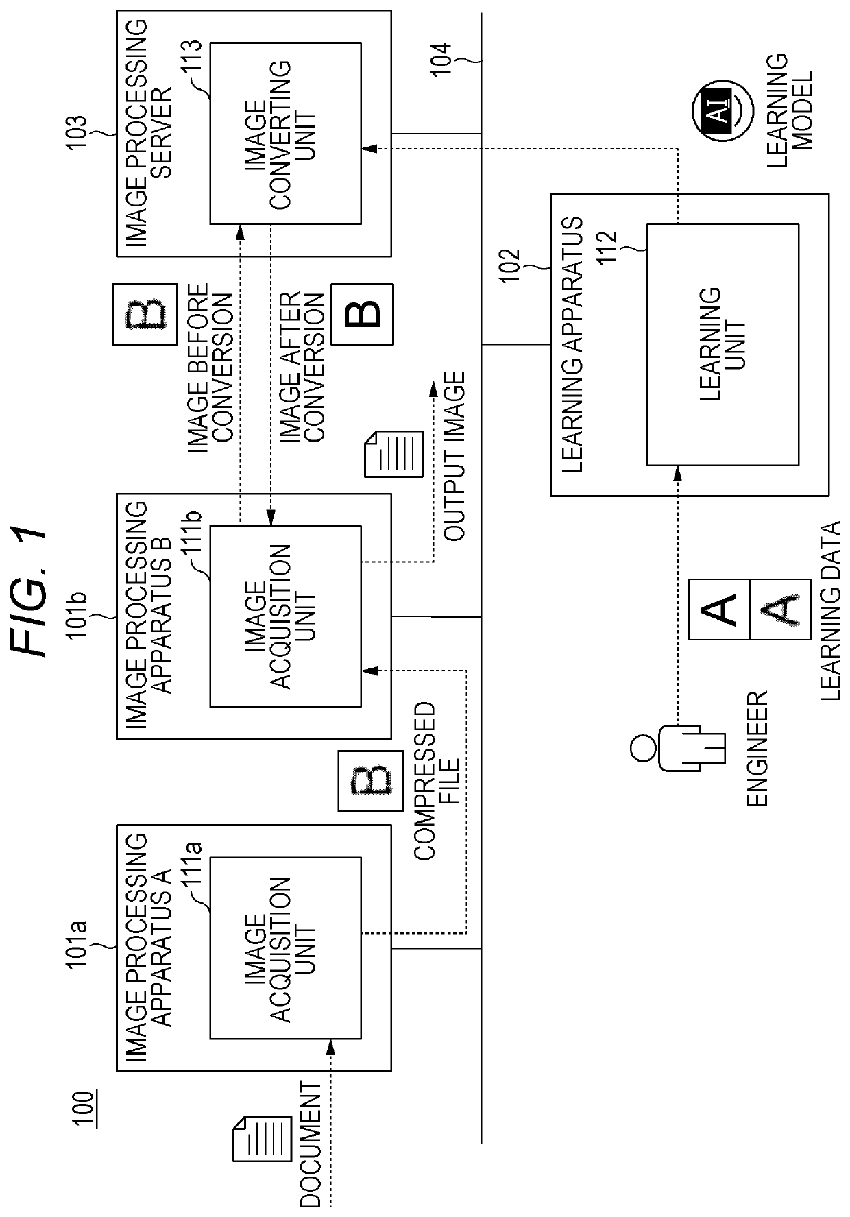
[0027]The present embodiment will describe an aspect in which a neural network which has learned in advance is used to convert an image having compression noise into an image from which the compression noise has been removed and output the image after conversion.
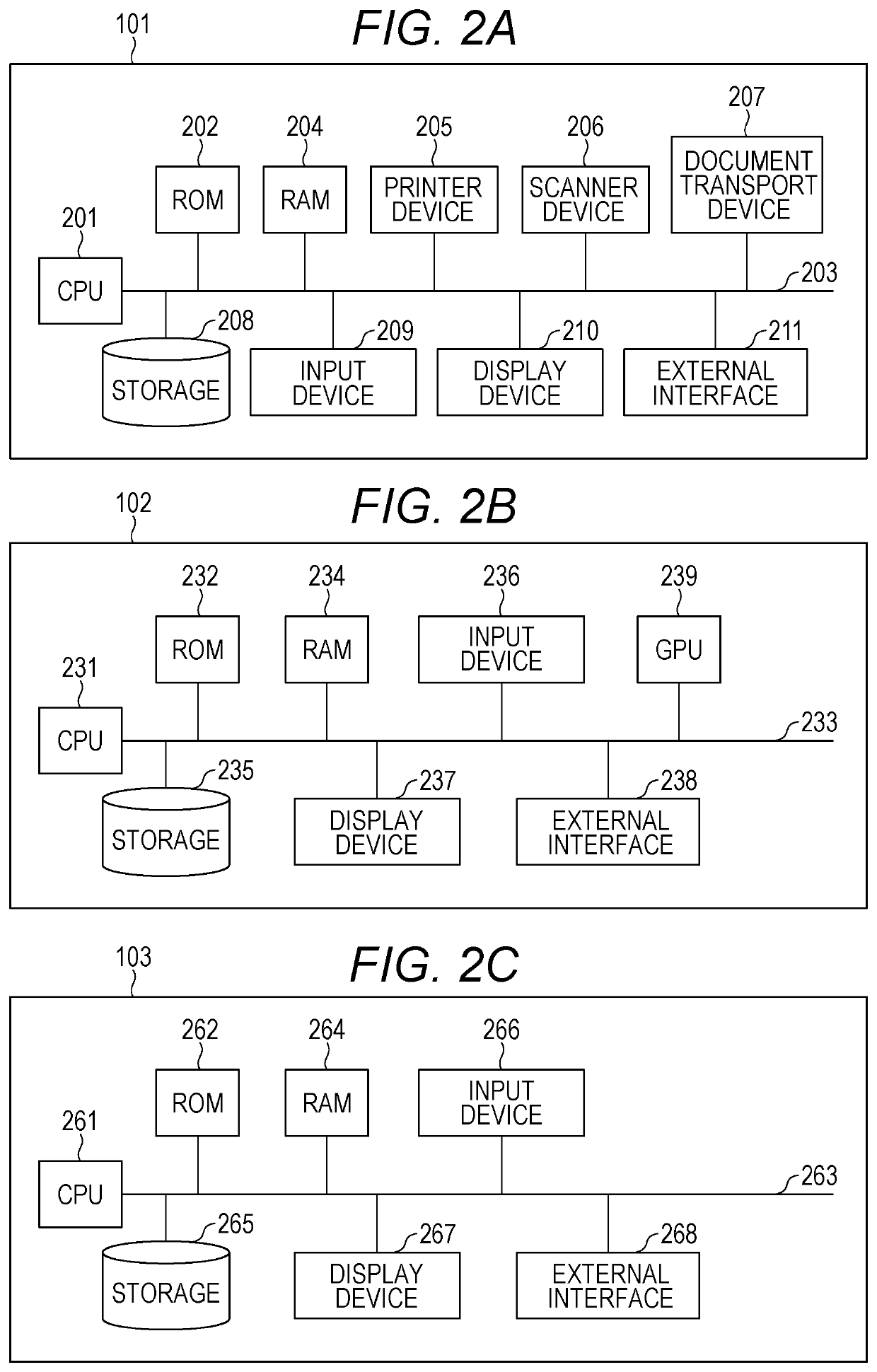
[0028]FIG. 1 is a diagram illustrating a configuration of an image processing system. As illustrated in FIG. 1, the image processing system 100 includes an image processing apparatus 101, a learning apparatus 102, and an image processing server 103 which are connected to each other via a network 104. Note that a plurality of the image processing apparatuses 101, the learning apparatuses 102, or the image processing servers 103 may be connected to the network 104, instead of a single image processing apparatus 101, learning apparatus 102, and image processing server 103. FIG. 1 illustrates a configuration example in which two of an image processing apparatus 101a and an image processing apparatus 101b are connected to t...
second embodiment
[0099]In the first embodiment, the example has been described in which image conversion is performed using one learning model. In the second embodiment, an example will be described in which image conversion is performed using a plurality of learning models (neural networks). Note that the image processing system 100 according to the second embodiment is identical to the image processing system 100 according to the first embodiment, except for the features described above.
[0100]
[0101]FIG. 12 is a table illustrating types of learning models. In the second embodiment, learning models A to N are used. These learning models are classified in consideration of information such as compression format (JPEG, WebP), compression quality (compression rate), and output source (output device, compression circuit, compression program). By preparing a plurality of learning models in this way, it becomes possible to perform image conversion suitable for a target image.
[0102]For example, the learning...
third embodiment
[0112]In the first and second embodiments, a description has been made that the engineer prepares the learning data in advance and inputs the learning data to the learning apparatus. In contrast, in the third embodiment, a PDL job received during operation of the image processing apparatus is used to automatically generate learning data. The configuration of the image processing system 100 according to the third embodiment is identical to the image processing systems 100 according to the first and second embodiments, except for the above-described feature portions and portions relating thereto. Therefore, similar configurations are denoted by similar reference numerals, and a detailed description thereof will be omitted.
[0113]100>
[0114]FIG. 14 is a diagram illustrating a configuration of an image processing system 100 according to a third embodiment. As illustrated in FIG. 14, the image processing system 100 includes an image processing apparatus 101, a learning apparatus 102, an im...
PUM
 Abstract
Description
Claims
Application Information
 - R&D
- Intellectual Property
- Life Sciences
- Materials
- Tech Scout
- Unparalleled Data Quality
- Higher Quality Content
- 60% Fewer Hallucinations
Browse by: Latest US Patents, China's latest patents, Technical Efficacy Thesaurus, Application Domain, Technology Topic, Popular Technical Reports.
© 2025 PatSnap. All rights reserved.Legal|Privacy policy|Modern Slavery Act Transparency Statement|Sitemap|About US| Contact US: help@patsnap.com