
Device for recording and graphic representation of pressure-volume curves

a technology of pressure-volume curves and pressure-volume curves, which is applied in the field of pressure-volume curve recording and display devices, can solve the problems of poor accuracy of measured values and large amount of expert knowledge for recording pressure-volume curves

Active Publication Date: 2022-09-20
LOWENSTEIN MEDICAL TECH SA
View PDF1 Cites 0 Cited by
  • Summary
  • Abstract
  • Description
  • Claims
  • Application Information

AI Technical Summary

Problems solved by technology

The accuracy of the measured values is presently poor and the recording of a pressure-volume curve requires a large amount of expert knowledge.

Method used


Image

  • Device for recording and graphic representation of pressure-volume curves
  • Device for recording and graphic representation of pressure-volume curves
  • Device for recording and graphic representation of pressure-volume curves

Examples


Embodiment Construction

[0053]The particulars shown herein are by way of example and for purposes of illustrative discussion of the embodiments of the present invention only and are presented in the cause of providing what is believed to be the most useful and readily understood description of the principles and conceptual aspects of the present invention. In this regard, no attempt is made to show details of the present invention in more detail than is necessary for the fundamental understanding of the present invention, the description in combination with the drawings making apparent to those of skill in the art how the several forms of the present invention may be embodied in practice.

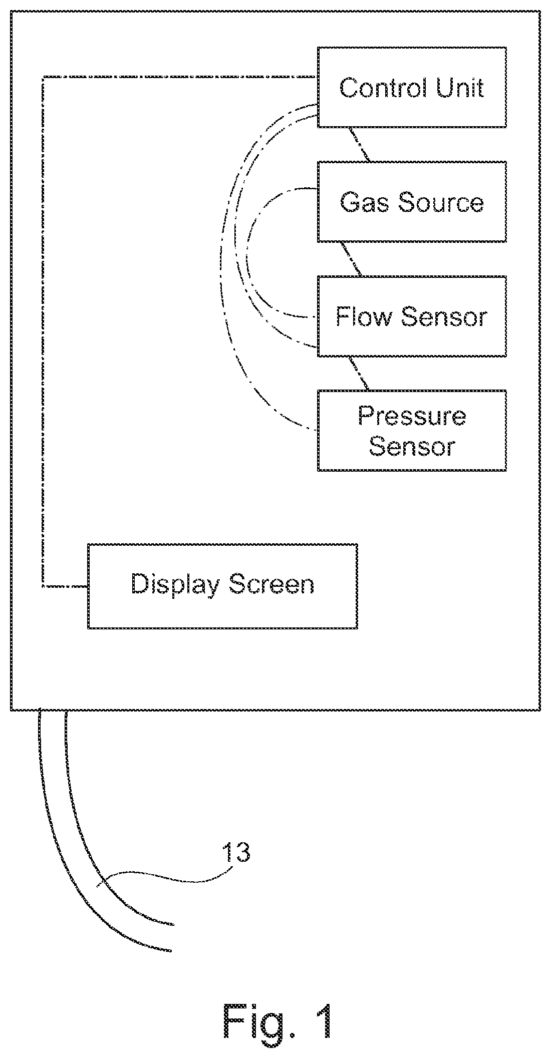
[0054]FIG. 1 shows a device for recording and displaying a pressure-volume curve (8), in which a gas stream (3) is generated by a gas source (1) under control of a control unit (2) and conveyed via a hose (13) to a patient, wherein a flow sensor (4) determines the gas stream (3) and the control unit (2) computes and record...


PUM


Abstract

A device for recording and displaying a pressure-volume curve, in which a gas stream is generated by a gas source under control of a control unit and conveyed via a hose to a patient, wherein a flow sensor determines the gas stream and the control unit computes and records the administered gas volume and wherein a pressure sensor determines the gas pressure and the control unit records the pressure and determines a pressure slope and determines a pressure-volume curve from the pressure and the volume and displays it on a display screen or stores it for a display.

Description

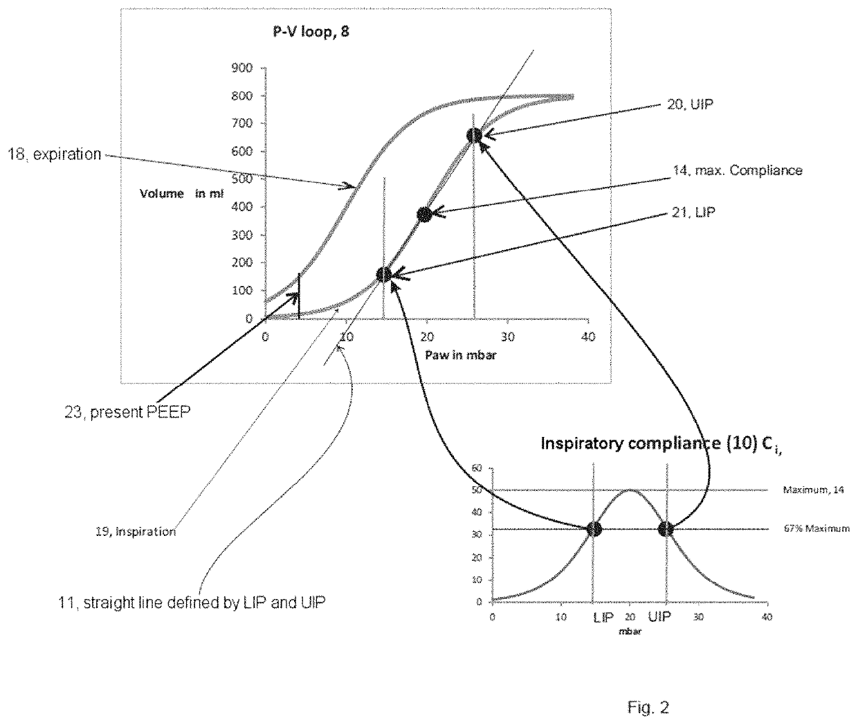
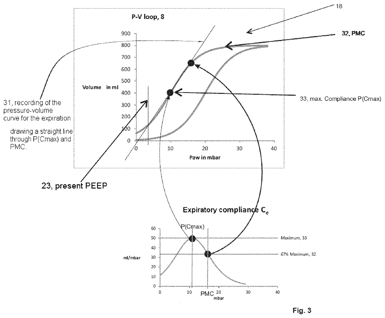
CROSS-REFERENCE TO RELATED APPLICATIONS[0001]The present application claims priority under 35 U.S.C. § 119 of German Patent Application No. 10 2018 001 909.9, filed Mar. 9, 2018, the entire disclosure of which is expressly incorporated by reference herein.BACKGROUND OF THE INVENTION1. Field of the Invention[0002]The present invention relates to a device for recording and displaying pressure-volume curves.2. Discussion of Background Information[0003]The recording of a pressure-volume curve (P / V curve) is a routine method for describing the respiratory-mechanical conditions of the respiratory tract. PV curves can typically be divided into three segments, which are separated from one another by two inflection points. There is usually a first segment having low compliance. This is adjoined by a middle, linear segment having greater compliance (CLIN). These two segments are separated by the lower inflection point (LIP). The middle steep component is ended by the upper inflection point (U...

Claims


Application Information

Patent Timeline
Patent Type & Authority Patents(United States)
IPC IPC(8): A61M16/00A61B5/08A61B5/00
CPCA61M16/024A61B5/0803A61B5/0816A61B5/743A61M16/0003A61M2016/003A61M2016/0027A61M2205/502A61B5/091A61B5/742A61M2016/0033A61M2205/52A61M2230/46A61M2205/3331
Inventor KREMEIER, PETER
Owner LOWENSTEIN MEDICAL TECH SA
Learn More