Measurement device, shape estimation device, measurement method, shape estimation method, and non-transitory recording medium recording program
a technology of measurement device and shape estimation, applied in the field of electric impedance tomography, can solve the problem of using wearable devices to estimate the shape of living bodies or other objects, and achieve the effect of performing simple and more accurate diagnosis
- Summary
- Abstract
- Description
- Claims
- Application Information
AI Technical Summary
Benefits of technology
Problems solved by technology
Method used
Image
Examples
first embodiment
[0099]Hereinafter, an EIT measurement device according to the first embodiment will be described with reference to the drawings.
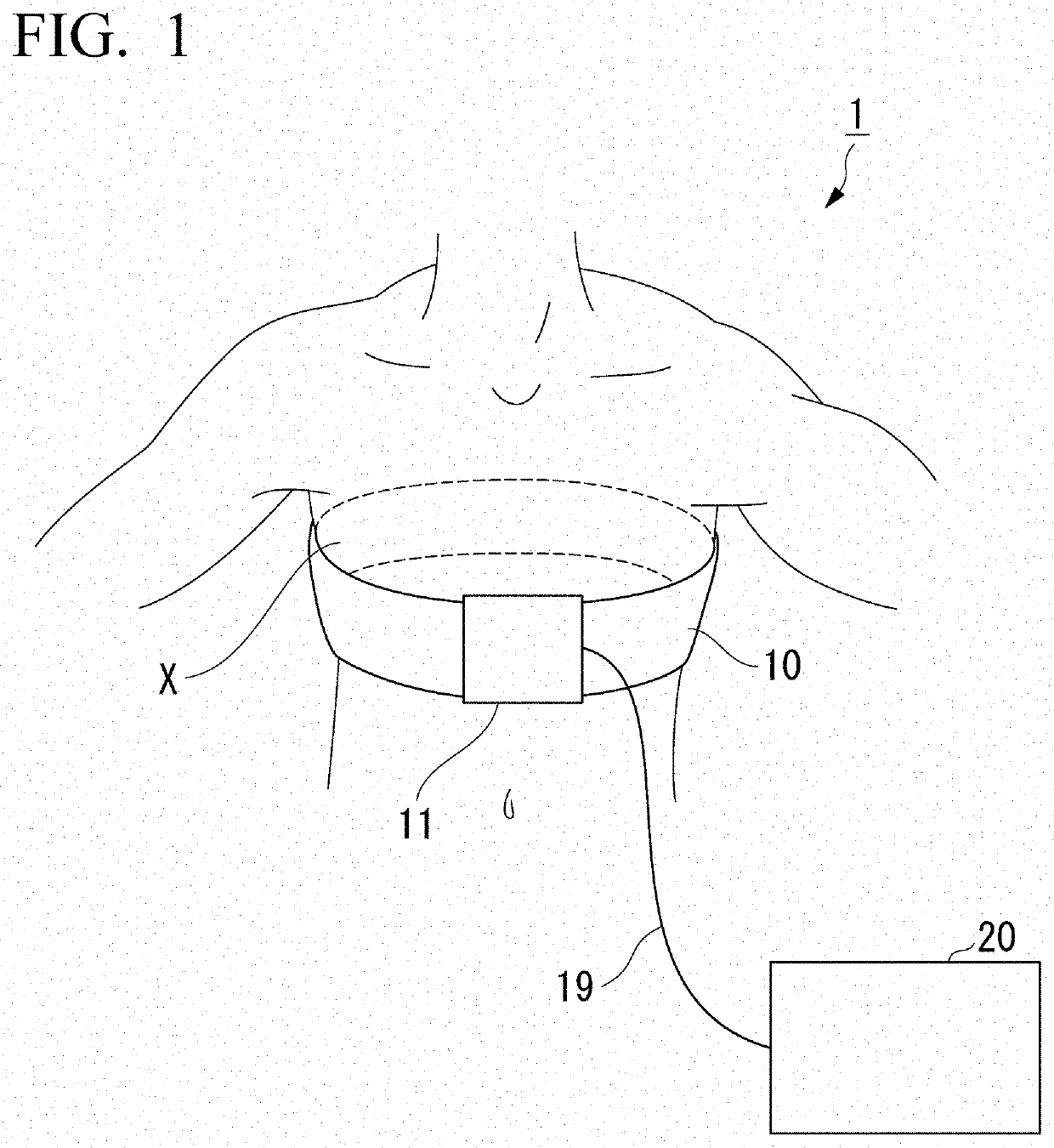
[0100]FIG. 1 is a diagram illustrating an entire configuration of the EIT measurement device according to the first embodiment. In FIG. 1, the EIT measurement device 1 is illustrated.
[0101]The EIT measurement device 1 includes a measurement belt 10 and an EIT measurement main body unit 20. As illustrated in FIG. 1, the measurement belt 10, for example, is wrapped around a portion (hereinafter referred to as a measurement target portion X) serving as a measurement target such as a chest portion of a measurement target person (living body) and used. The measurement belt 10 is connected to the EIT measurement main body unit 20 via a measurement circuit 11 and a signal cable 19.
[0102]The measurement belt 10 may be configured with an adjustable wrapping length to be used after being wrapped around a head portion, an arm, a leg, or the like in addition to the che...
second embodiment
[0217]Next, an EIT measurement device 1 according to the second embodiment will be described with reference to the drawings. Also, the same function components as those of the first embodiment are assigned the same reference signs and description thereof will be omitted.
[0218]FIG. 18 is a diagram illustrating a functional configuration of a measurement belt according to the second embodiment.
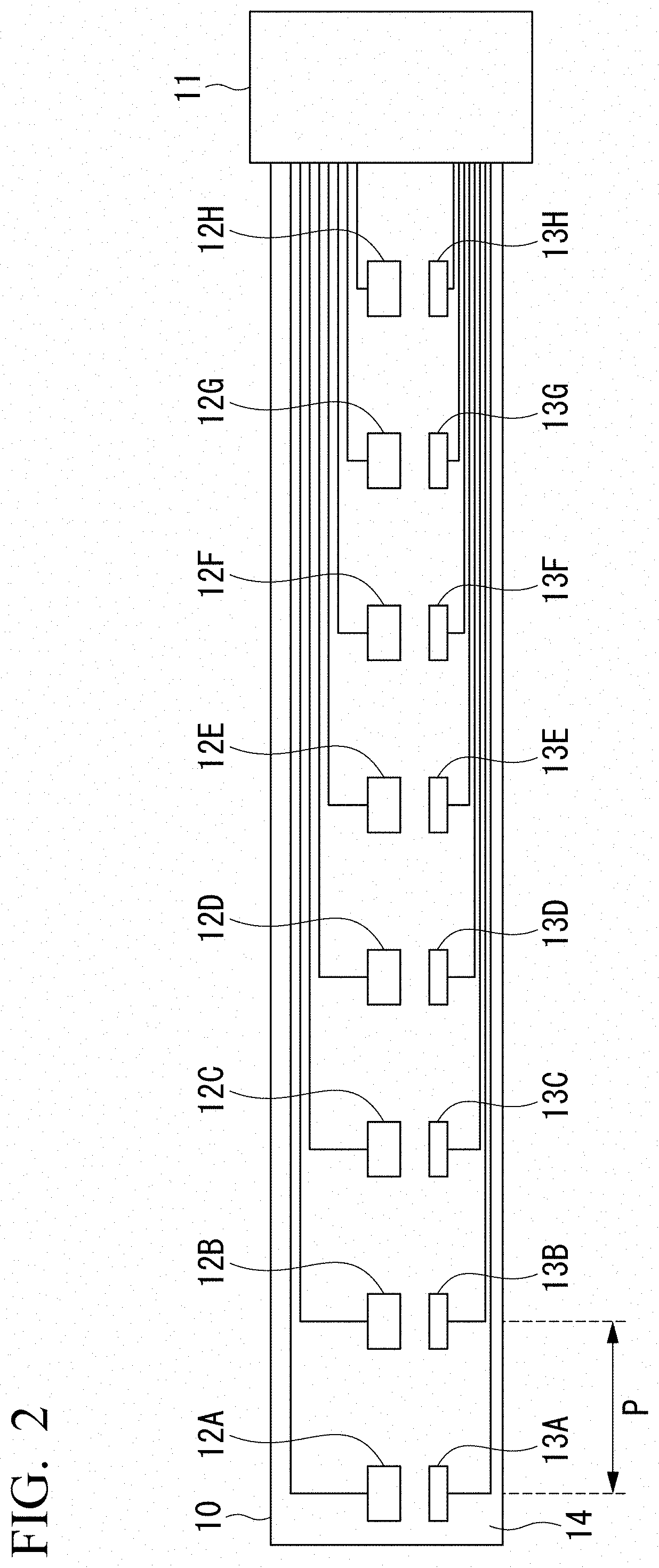
[0219]Also, the notation of electrode pads 12A to 12H and strain gauges 13A to 13H is omitted to avoid a complexity in the drawings in FIG. 18, but the electrode pads 12A to 12A and the strain gauges 13A to 13H are configured to be actually periodically arranged on a flexible substrate 14 as in the first embodiment.
[0220]As illustrated in FIG. 18, a measurement belt 10 according to this embodiment includes perimeter measurement electrode pads 301, 302, . . . , 30f attached to the measurement belt 10 and periodically arranged at intervals α in a longitudinal direction of the measurement belt 10 (...
third embodiment
[0235]As described above, in the relative position specifying process S1 according to the first embodiment, an EIT measurement device 1 arranges references points N13A and N13E on the x-axis and arranges reference points N13C and N13G on the y-axis orthogonal to the x-axis when virtual positions on the xy coordinates of alternately designated strain gauges (strain gauges 13A, 13C, 13E, and 13G (FIG. 2)) are provisionally determined (see FIG. 7). That is, the EIT measurement device 1 according to the first embodiment performs calculation under the assumption that four (strain gauges 13A, 13C, 13E, and 13G) of the strain gauges periodically arranged on the measurement belt 10 are constantly arranged on axes (x- and y-axes) orthogonal to each other when the measurement belt 10 is wrapped around the measurement target portion X.
[0236]However, the periodic intervals (distances P) between the strain gauges 13A to 13H periodically arranged in the measurement belt 10 are fixed and a perimet...
PUM
 Abstract
Description
Claims
Application Information
 - R&D
- Intellectual Property
- Life Sciences
- Materials
- Tech Scout
- Unparalleled Data Quality
- Higher Quality Content
- 60% Fewer Hallucinations
Browse by: Latest US Patents, China's latest patents, Technical Efficacy Thesaurus, Application Domain, Technology Topic, Popular Technical Reports.
© 2025 PatSnap. All rights reserved.Legal|Privacy policy|Modern Slavery Act Transparency Statement|Sitemap|About US| Contact US: help@patsnap.com


