
Temperature measuring device and temperature measuring arrangement

a technology of temperature measurement and temperature measurement, which is applied in the direction of secondary cell servicing/maintenance, instruments, batteries, etc., can solve the problems of difficult to and heat is difficult to dissipate, so as to reduce the probability of electricity flow, accurately and quickly measure the temperature of the object, and high thermal conductivity

Active Publication Date: 2022-10-25
NOK CORP
View PDF21 Cites 0 Cited by
  • Summary
  • Abstract
  • Description
  • Claims
  • Application Information

AI Technical Summary

Benefits of technology

[0005]Accordingly, the present invention provides temperature measuring devices and temperature measuring arrangements that can accurately and quickly measure the temperature of an object for which the temperature is to be measured, can reduce the probability of flow of electricity in the object for which the temperature is to be measured, and can measure the temperature with a small amount of contact pressure applied to the object for which the temperature is to be measured.
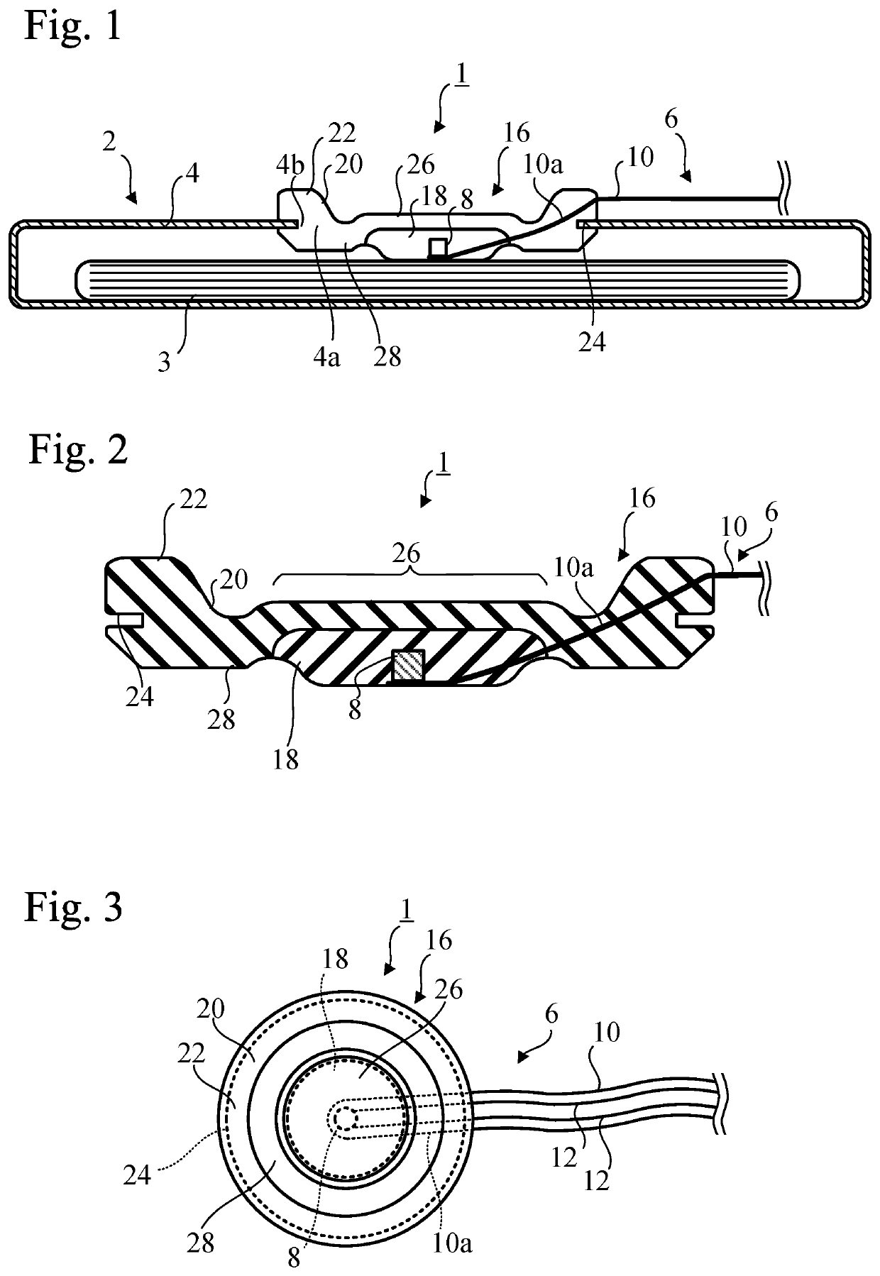
[0007]In this aspect, the heat transfer part having a high thermal conductivity allows heat to be conducted well from the object for which the temperature is to be measured to the temperature sensitive section, whereas the heat is difficult to dissipate by thermal conduction from the heat transfer part by means of the heat insulation part covering a single side of the heat transfer part. Therefore, it is possible to accurately and quickly measure the temperature of the object for which the temperature is to be measured. In addition, since the temperature sensitive section is embedded in the heat transfer part, electrical contact can be avoided between the object for which the temperature is to be measured and the temperature sensitive section. Therefore, it is possible to reduce the probability of the flow of electricity from the electrical temperature measuring instrument to an object for which the temperature is to be measured for which inflow of electricity from outside should be avoided, such as a battery. Furthermore, since the heat insulation part and the heat transfer part are formed of elastomeric materials, the contact pressure on the object of which the temperature is to be measured is small even if the heat transfer part is in contact with the object of which the temperature is to be measured. Furthermore, since the heat insulation part is formed of an elastomer material with a high elasticity, it is easy to mount the mounting section formed at the heat insulation part on the mounting location.

Problems solved by technology

However, when there is a large distance between the object for which the temperature is to be measured and the temperature sensitive section, it is difficult to measure the temperature accurately and quickly.
In this aspect, the heat transfer part having a high thermal conductivity allows heat to be conducted well from the object for which the temperature is to be measured to the temperature sensitive section, whereas the heat is difficult to dissipate by thermal conduction from the heat transfer part by means of the heat insulation part covering a single side of the heat transfer part.

Method used


Image

  • Temperature measuring device and temperature measuring arrangement
  • Temperature measuring device and temperature measuring arrangement

Examples


Embodiment Construction

[0013]Hereinafter, with reference to the accompanying drawings, an embodiment according to the present invention will be explained.

[0014]As shown in FIG. 1, a temperature measurement device 1 according to an embodiment of the present invention is used for measuring the temperature of a battery 3 (the object for which the temperature is to be measured) of a battery unit 2 mounted in a automotive vehicle (for example, an electric vehicle or a hybrid vehicle). The battery unit 2 includes the battery 3 and a metal case 4 containing the battery 3. The battery 3 is, for example, a secondary battery, and is, for example, a laminate type lithium ion battery. In the following description, the combination of the temperature measurement device 1 and the battery unit 2 may be referred to as a “temperature measuring arrangement”.

[0015]The case 4 of the battery unit 2 has a thin rectangular parallelepiped shape. In the ceiling plate of the case 4, a mounting hole (mounting location) 4a for deploy...


PUM

PropertyMeasurementUnit
resistivityaaaaaaaaaa
temperatureaaaaaaaaaa

Abstract

A temperature measuring device includes an electrical temperature measuring instrument configured to measure the temperature of a temperature sensitive section electrically; a heat transfer part formed of an elastomer in which the temperature sensitive section is embedded; and a heat insulation part formed of an elastomer covering a single surface of the heat transfer part. The heat transfer part has a thermal conductivity that is greater than a thermal conductivity of the heat insulation part. A mounting section is formed at the heat insulation part, and is to be mounted at a mounting location.

Description

CROSS REFERENCE TO RELATED APPLICATIONS[0001]This application is a U.S. National Phase application of International Application No. PCT / JP2018 / 044611, filed on Dec. 4, 2018 and published in Japanese as WO2019 / 111909 A1 on Jun. 13, 2019 and claims priority to Japanese Patent Application No. 2017-234482, filed on Dec. 6, 2017. The entire disclosures of the above applications are expressly incorporated by reference herein.BACKGROUNDTechnical Field[0002]The present invention relates to temperature measuring devices and to temperature measuring arrangements.Related Art[0003]JP-A-2010-54270 and JP-A-2010-190788 disclose techniques for measuring the temperature of a battery mounted in an automotive vehicle.SUMMARY[0004]There is a growing demand for accurate and rapid measurement of temperatures of objects for which temperatures are to be measured. In addition, for a particular object for which temperature is to be measured, such as a battery, in which flow of electricity from the outside s...

Claims


Application Information

Patent Timeline
Patent Type & Authority Patents(United States)
IPC IPC(8): G01K1/16G01K1/14
CPCG01K1/16G01K1/14H01M10/486H01M10/0525H01M50/105H01M50/224H01M2220/20H01M10/425Y02E60/10
Inventor YAMAMOTO, HIROKI
Owner NOK CORP
Learn More